
Controller device of traffic signal equipment

a technology of traffic signal and control device, which is applied in the field of control device for controlling traffic signal equipment, can solve the problems of requiring position detectors to be placed all over the crosswalk with a lot of cost, and traffic accidents of elderly or handicapped people have become social problems, so as to prevent wasteful extension of display and prevent start

Inactive Publication Date: 2006-09-28
FUJITSU LTD
View PDF3 Cites 30 Cited by
  • Summary
  • Abstract
  • Description
  • Claims
  • Application Information

AI Technical Summary

Benefits of technology

[0010] An object of the present invention is to realize a traffic signal system that can switch traffic signals at an appropriate time interval so as to have a balance between pedestrian's safety in walking across a road and vehicles' smooth traffic along the road.
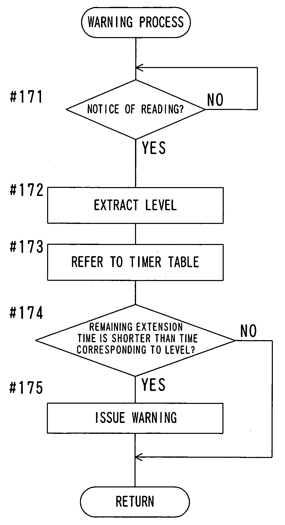
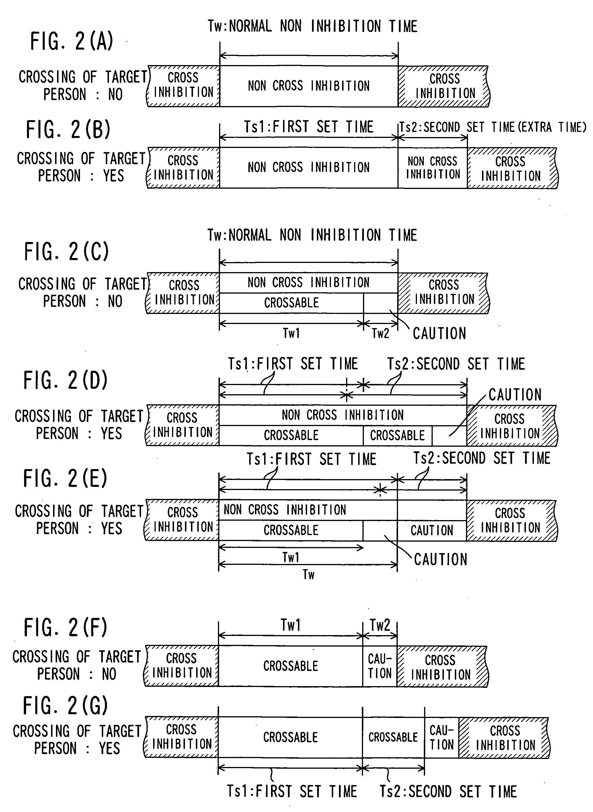
[0013] When the traverser detecting device detects crossing of the target person of extension during the first time period while the non cross inhibition signal is displayed, the controller device that received the notice elongates the display period of the non cross inhibition signal from the end of the first time period until the second set time passes. The extension of the non cross inhibition period enables an elderly people or a handicapped person who cannot walk fast to cross a road in good time. In particular, the extension of the non cross inhibition period is useful in a wide road having a long crossing distance. The target person of extension is a pedestrian who needs the extension of the non cross inhibition period. On the other hand, the extension of the non cross inhibition period is restricted by the second set time, so that the traffic of vehicles is not interrupted so long.
[0014] A more preferable controller device stores level information contained in the detection signal responding to the reception of the detection signal from the traverser detecting device in the first time period, and then time corresponding to the level information is set as the second set time. A still more preferable controller device sets the longest time period among plural time periods corresponding to level information of the plural detection signals as the second set time if plural detection signals that respectively indicate plural target persons of extension are received from the traverser detecting device during the first time period. The time setting corresponding to the level information has an effect of preventing a wasteful extension of the display of the non cross inhibition signal.
[0015] Another more preferable controller device stores identification information of the target person of extension and the level information contained in the detection signal in connection with each other responding to the reception of the detection signal from the traverser detecting device during the first time period. If a detection signal containing the identification information of the target person of extension that is stored at the time is received from the traverser detecting device during the first time period, the stored information about the identification information of the target person of extension and the corresponding level information is erased. After the first time period, a time period corresponding to the level information stored at the time is set as the second set time. This controller device has an effect of preventing start of elongating the non cross inhibition signal after the target person of extension finishes the crossing.
[0016] According to the present invention, it is possible to realize a traffic signal system that can switch traffic signals at an appropriate time interval so as to have a balance between pedestrian's safety in walking across a road and vehicles' smooth traffic along the road.

Problems solved by technology

Recently, traffic accidents of elderly people or handicapped people have become social problems.
In order to check the position of the pedestrian, however, position detectors are required to be placed all over the crosswalk with a lot of cost.

Method used


Image

  • Controller device of traffic signal equipment
  • Controller device of traffic signal equipment
  • Controller device of traffic signal equipment

Examples


Embodiment Construction

[0028] Hereinafter, the present invention will be explained more in detail with reference to embodiments and drawings.

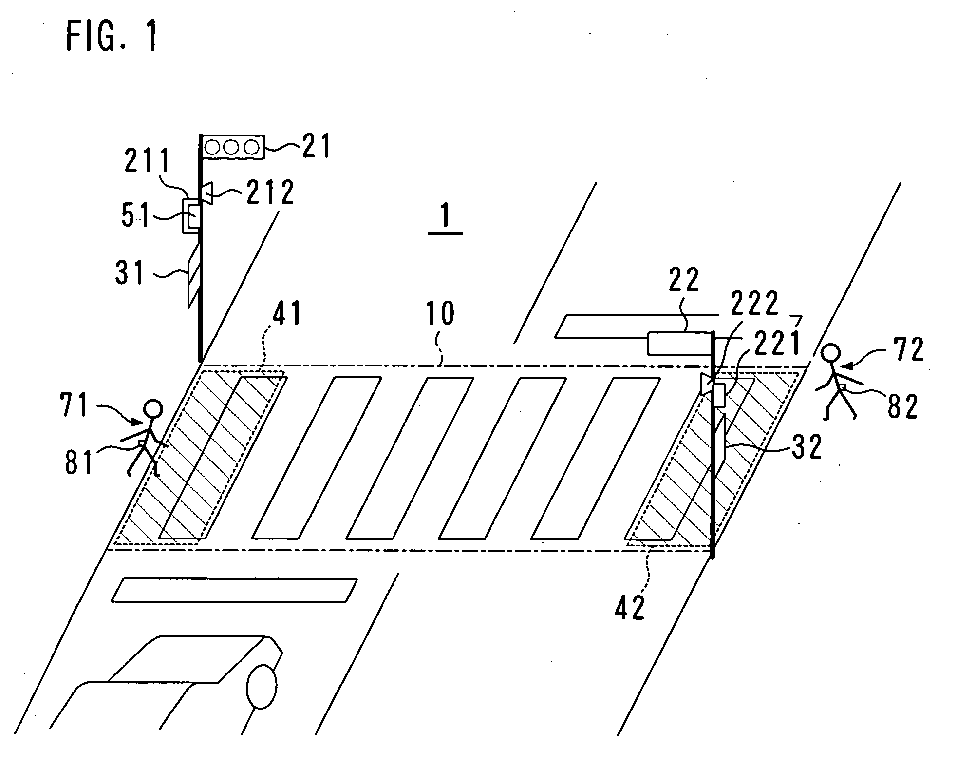
[0029]FIG. 1 shows a structure of a traffic signal system according to the present invention. The traffic signal system 1 exemplified in FIG. 1 is a system for controlling traffic signals in a crosswalk 10.

[0030] The traffic signal system 1 is equipped with traffic signal equipment 21 and 22 for vehicles, traffic signal equipment 31 and 32 for pedestrians, reader devices 41 and 42 as traverser detecting devices, a controller device 51, and transmitting devices 81 and 82.

[0031] Each piece of the traffic signal equipment 21 and 22 includes three types of indicator lights having different colors for displaying three types of traffic signals. A control box 211 and an audio output device 212 are attached to a mast for supporting the indicator lights of the traffic signal equipment 21. In the same manner, a control box 221 and an audio output device 222 are attached to ...


PUM


Abstract

A controller device, after switching a traffic signal displayed on traffic signal equipment from a cross inhibition signal to a non cross inhibition signal, makes the traffic signal equipment display the non cross inhibition signal during a second time period before a second set time passes after a first time period ends to switch from the non cross inhibition signal to the cross inhibition signal responding to end of the second time period, if a detection signal indicating a target person of extension is received from a traverser detecting device during the first time period before a first set time passes after switching from the cross inhibition signal to the non cross inhibition signal. If no detection signal is received during the first time period, the controller device switches from the non cross inhibition signal to the cross inhibition signal responding to end of the first time period.

Description

BACKGROUND OF THE INVENTION [0001] 1. Field of the Invention [0002] The present invention relates to a controller device for controlling traffic signal equipment that is installed on a road and has a characteristic in signal control for pedestrians. [0003] 2. Description of the Prior Art [0004] Recently, traffic accidents of elderly people or handicapped people have become social problems. It has become important more and more to secure traffic safety of elderly people as a population ratio of elderly people increases. For this reason, control of the traffic signal equipment at crosswalks is being improved. [0005] In general, traffic signal equipment has a function to display a first traffic signal (a red signal) that indicates stop, a second traffic signal (a green signal) that indicates go and a third traffic signal (a yellow signal or a blinking green signal) that warns that the signal will change to the first traffic signal soon. The traffic signal equipment is usually controlle...

Claims


Application Information

Patent Timeline
IPC IPC(8): G08G1/00
CPCG08G1/07G08G1/095
Inventor UEDA, SHINYATOGAWA, SHINJIMATSUDA, TAKAOYANAGIHARA, MITSUNORI
Owner FUJITSU LTD
Learn More