
Communication system and communication method

a communication system and communication method technology, applied in the field of communication system and communication method, can solve the problems of unguaranteed packet delivery, large overhead, and insufficient best effort service to cater for the requirements of these applications, and achieve the effect of not unnecessarily congested traffi

Inactive Publication Date: 2006-09-28
PANASONIC CORP
View PDF4 Cites 129 Cited by
  • Summary
  • Abstract
  • Description
  • Claims
  • Application Information

AI Technical Summary

Benefits of technology

[0011] In order to resolve the problems mentioned above, the QoS controller module needs to be transferred from the network to the terminal. The terminal will be made aware of traffic conditions, and the necessary corrections need to be handled at the terminal instead of passing the responsibility to the network. This will have the advantage of not unnecessarily congesting the traffic, and do away on the reliance on network management system to handle all QoS related functionalities.

Problems solved by technology

In best effort service, the delivery of packets is not guaranteed.
Best effort service, however, is not sufficient to cater for the requirements of these applications.
This will cause a large amount of overheads just to maintain each state of each flow.
This makes IntServ solution very unscalable.
Moreover, the RSVP requires support on every node along the data path, which is not always possible in the large and complicated systems.
This kind of uncoordinated control is inefficient not optimised.
This could not solve the problem completely.
For example, if the congestion were caused by a terminal sending too fast, to perform network dropping or queuing would only make the terminal or another terminal to suffer bad service experience.

Method used


Image

  • Communication system and communication method
  • Communication system and communication method
  • Communication system and communication method

Examples


Embodiment Construction

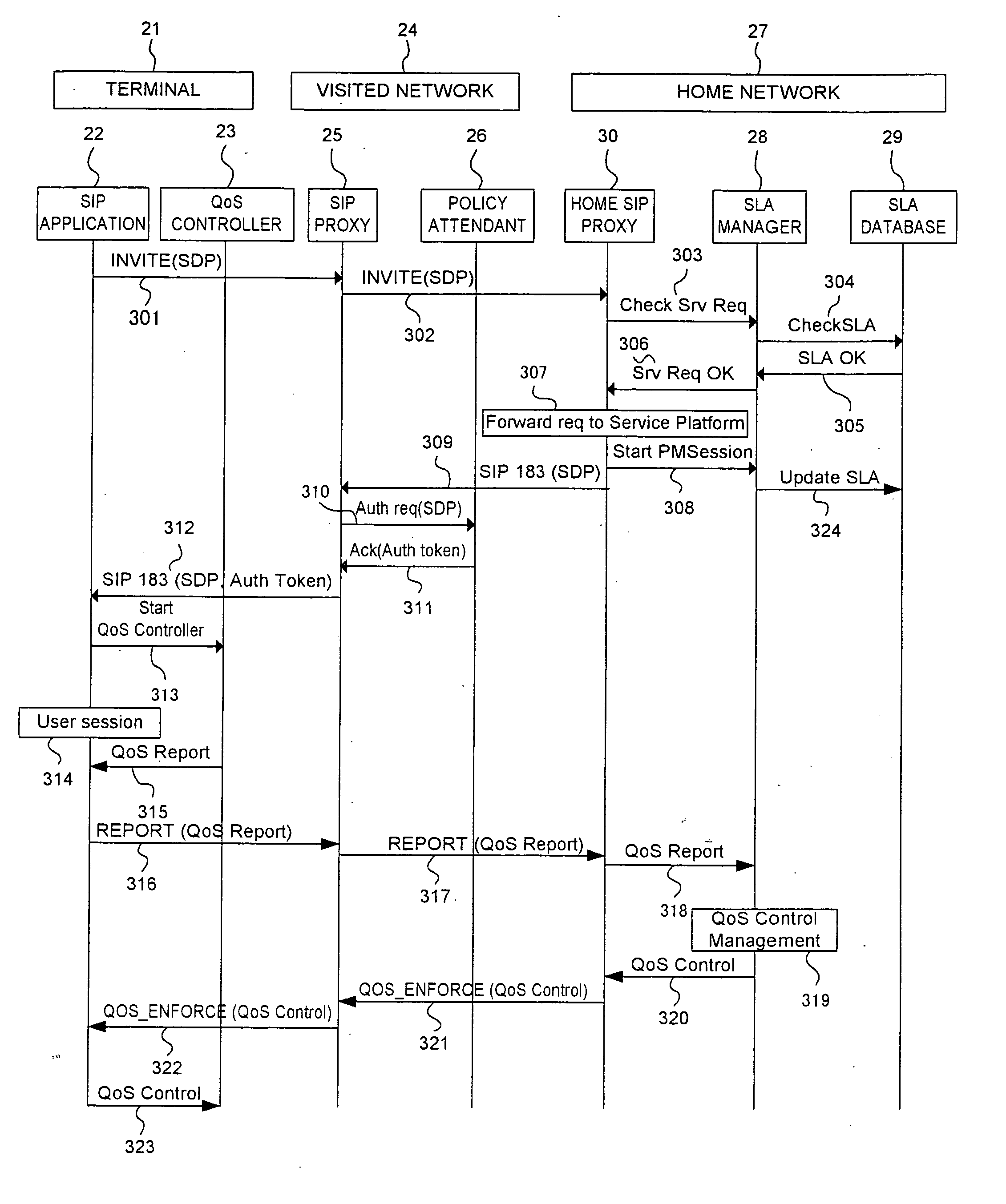
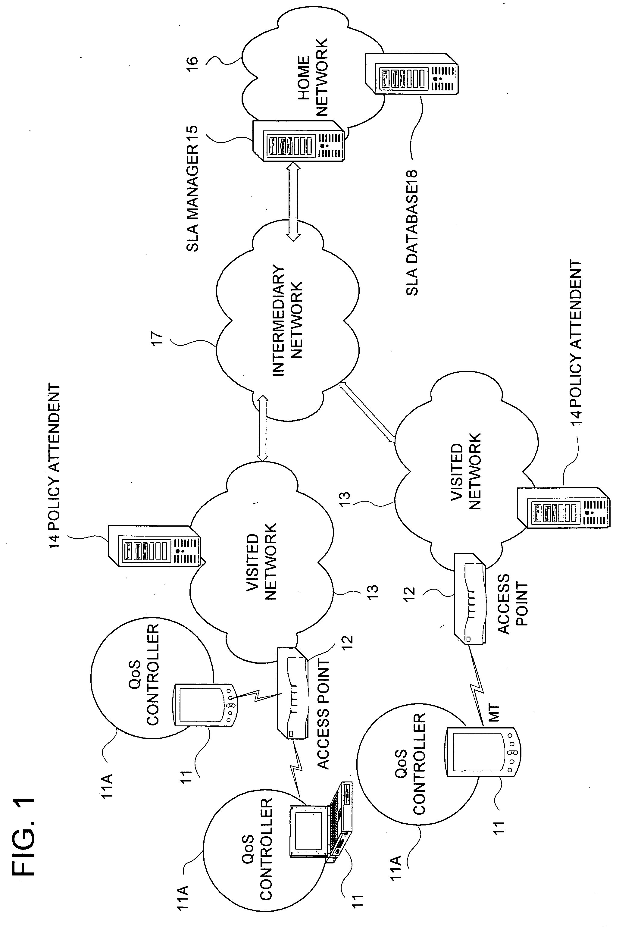
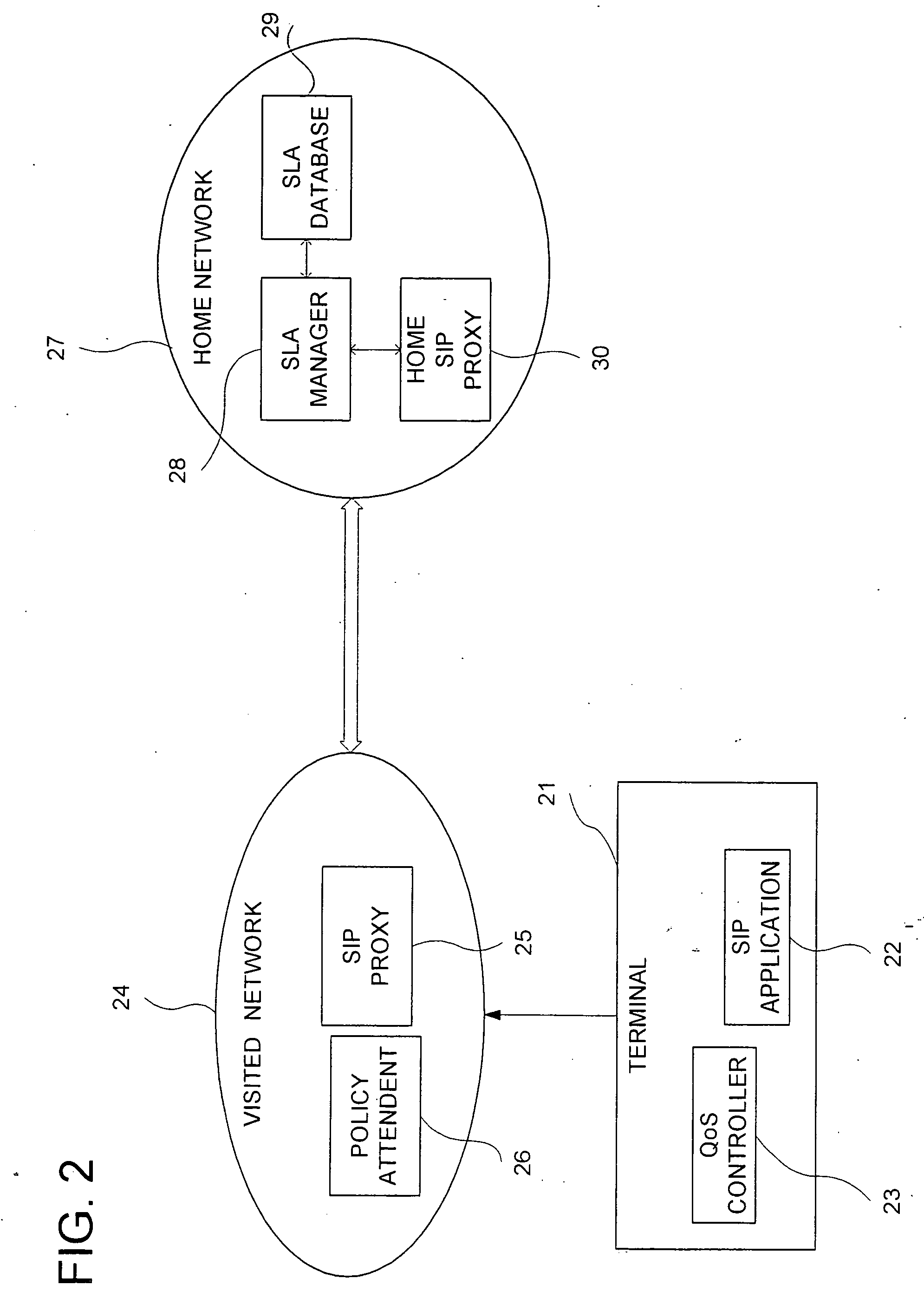
[0026] In this invention, the QoS management functions are transferred to the terminal for more effective end-to-end QoS management. The mobile terminal will be equipped with QoS management capabilities such as managing its transmission rate and also its receiving rate by controlling the number of incoming request. In this invention, there is a central server to monitor all terminals directly based on the service level agreement between the user of the mobile terminal and the service provider. The central server resides at the user's home network, which is the network where the user subscribes its service from. The terminal will have a QoS controller module performing the reporting and monitoring. This QoS controller also reacts to behavioural changes when it receives enforcement data that tells the terminal what values it should change to. The QoS controller will then operate within the threshold and boundary of the new values.

[0027] In the following, an apparatus and a method for...


PUM


Abstract

A technique for the end terminal provided with services to handle QoS process is disclosed. According to this technique, a terminal based QoS management scheme is implemented to achieve end-to-end QoS wherein the end terminal 21 is responsible for handling of the QoS related functions. In order for QoS management to be handled at terminal, the terminal needs to know the network conditions and external state of entities in order to know what action to be taken. For example, the terminal performs monitoring and usage collection. These performance data are then reported to a central server (SLA manager 28). The central server collects these data from all terminals within its administration domain. The central server also has access to information on the QoS to be given to individual terminals, such as service level. Based on the information, the central server decides what action to be taken by individual terminal and enforces these actions into the affected terminals.

Description

TECHNICAL FIELD [0001] This invention relates to a communication system and a communication method, especially a radio communication system and a radio communication method utilizing the wireless technology in a mobile network. This invention can also be used in a heterogeneous network environment to provide end-to-end QoS guarantees. BACKGROUND ART [0002] IP networks were originally designed to carry best effort traffic. In best effort service, the delivery of packets is not guaranteed. For applications that are delay sensitive such as real-time multimedia applications, data needs to arrive within a specified delay bound in order for it to be useful. Therefore, these applications need some level of service guarantee from the network that this data is likely to arrive on time in order to be useful. Best effort service, however, is not sufficient to cater for the requirements of these applications. [0003] Therefore, Quality of Service (QoS) support has become an essential component i...

Claims


Application Information

Patent Timeline
Patent Type & Authority Applications(United States)
IPC IPC(8): G06F15/16H04L12/801H04L12/851H04L12/911H04W24/00H04W28/18H04W28/24
CPCH04L47/10H04L47/11H04L47/12H04L47/14H04L47/20H04L47/2416H04L47/2425H04L47/2441H04L47/32H04L47/745H04L47/762H04L47/781H04L47/805H04L47/824H04W28/18H04W28/24H04W28/02H04W72/54H04W8/04
Inventor CHIA, PIE YENCHENG, HONG
Owner PANASONIC CORP
Learn More