Method and apparatus for monitoring the quantity of differential data in a storage system
a storage system and differential data technology, applied in the field of storage systems, can solve the problem that the storage memory area cannot provide a suitable snapsho
- Summary
- Abstract
- Description
- Claims
- Application Information
AI Technical Summary
Benefits of technology
Problems solved by technology
Method used
Image
Examples
1st embodiment
1st Embodiment
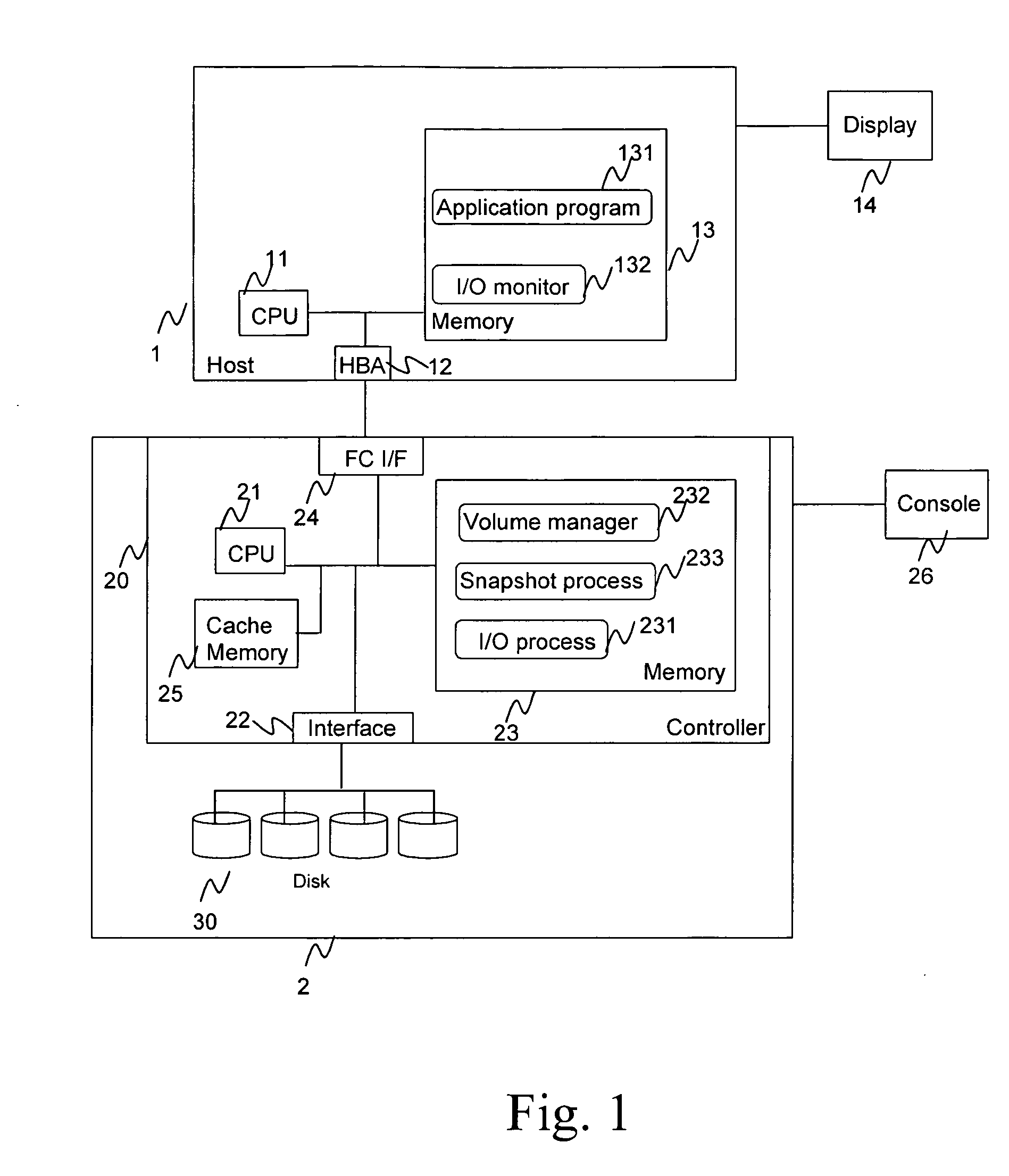
[0024]FIG. 1 shows an example of the information system in which the method of the present invention can be applied. A Host 1 comprises a CPU 11 to provide the general data processing capability of a host computer, such as execution of various computer executable programs. A host bus adapter (HBA) 12 provides a suitable interface for connection to a storage component. A memory 13 typically includes random access memory (RAM) for volatile memory storage. A display 14 allows a user to interact with the host computer. Additional components not shown are understood to be included, such as a keyboard, mouse, and other suitable input devices.
[0025] A storage system 2 comprises a disk controller 20 and a disk subsystem 30 which comprises a plurality disks (physical storage devices). The disk controller 20 comprises a CPU 21 to provide the disk controller functionality. A backend interface 22 connects to the disk subsystem 30. Programs comprising the disk controller functions...
2nd embodiment
2nd Embodiment
[0083] The system configuration of the information system according to a second embodiment of the present invention is the same as the one in the first embodiment. In the second embodiment, the estimate of the size of the preservation volume by I / O monitor 132 is performed differently. In the first embodiment, the I / O monitor 132 makes its observations in real time as the storage system 2 is taking snapshot. For example, when the storage system 2 takes snapshots as shown in FIG. 6, seven snapshots are taken from the volume in the first row in FIG. 6 (whose Port WWN 601 and LUN 602 is 10:04:e2:04:48:39 and 0 respectively) and each snapshot is taken every 24 hours. That is, it takes 24×7=168 hours to collect the seven snapshots, and the I / O monitor 132 must observe I / O activity for 168 hours. To reduce the observation time, the I / O monitor 132 in accordance with the second embodiment observes the write activities for a shorter length of time (like a couple of hours or wi...
3rd embodiment
3rd Embodiment
[0091]FIG. 12 shows the system configuration of the information system in accordance with a third embodiment of the present invention. The difference of the system in the third embodiment from the first or second embodiment is that the I / O monitor 234 executes in the storage system 2, whereas the I / O monitor 132 in the 1st and 2nd embodiment executes in the host computer 1. In this 3rd embodiment, the task of observing write I / O activities is performed within the storage system 2.
[0092] The process of the I / O monitor 234 is almost the same as the one in the 1st or 2nd embodiment. However, at step 801 in FIG. 8, since the I / O monitor 234 and snapshot process 233 resides in the same disk controller 20, the I / O monitor 234 can acquire the input parameters, such as Port WWN 601, LUN 602, BLOCK Size 603, and so on, from the snapshot process 233 if the instructions to create snapshots has already come to the snapshot process 233 from users. In this case, users do not need t...
PUM
 Abstract
Description
Claims
Application Information
 - R&D
- Intellectual Property
- Life Sciences
- Materials
- Tech Scout
- Unparalleled Data Quality
- Higher Quality Content
- 60% Fewer Hallucinations
Browse by: Latest US Patents, China's latest patents, Technical Efficacy Thesaurus, Application Domain, Technology Topic, Popular Technical Reports.
© 2025 PatSnap. All rights reserved.Legal|Privacy policy|Modern Slavery Act Transparency Statement|Sitemap|About US| Contact US: help@patsnap.com


