Internal combustion engine with variable volume prechamber

a technology of internal combustion engine and prechamber, which is applied in the direction of combustion engine, engine controller, machine/engine, etc., can solve the problems of incomplete combustion turbulence within the main combustion chamber, and often harmful oxides of nitrogen in the internal combustion engine,

Inactive Publication Date: 2006-10-05
CATERPILLAR INC
View PDF13 Cites 53 Cited by
  • Summary
  • Abstract
  • Description
  • Claims
  • Application Information

AI Technical Summary

Benefits of technology

[0009] According to one exemplary aspect of the invention, an internal combustion engine is provided. The engine may comprise a piston cylinder formed within an engine block, an engine head secured to the engine block, a primary piston configured to slide within the piston cylinder, a main combustion chamber—which is defined by the primary piston, piston cylinder, and engine head—a variable volume prechamber formed within the engine head and in fluid communication with the main combustion chamber, an ignition device configured to ignite a fuel within the prechamber, and a prechamber piston configured to translate within the prechamber. In this exemplary aspect, translation of the prechamber piston within the prechamber varies the volume within the prechamber. The prechamber may also comprise at least one orifice for providing fluid communication between the prechamber and main combustion chamber.

Problems solved by technology

Internal combustion engines often emit harmful oxides of nitrogen (“NOx”) during operation.
Unfortunately, using a lean air-to-fuel ratio may result in incomplete combustion within the main combustion chamber, especially in engines with large bores, due to the relatively slow rate of flame propagation from a single point ignition source, such as a spark plug.
Furthermore, turbulence within the main combustion chamber may extinguish the ignition flame before the lean gas or gaseous fuel combusts.
These prechambers, however, do not have adjustable volumes that may vary as a function of different engine operating conditions.

Method used


Image

  • Internal combustion engine with variable volume prechamber
  • Internal combustion engine with variable volume prechamber
  • Internal combustion engine with variable volume prechamber

Examples


Embodiment Construction

[0020] Reference will now be made in detail to embodiments of the invention, examples of which are illustrated in the accompanying drawings. Wherever possible, the same reference numbers will be used throughout the drawings to refer to the same or like parts.

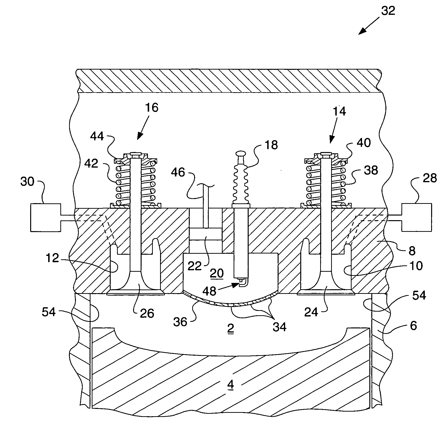
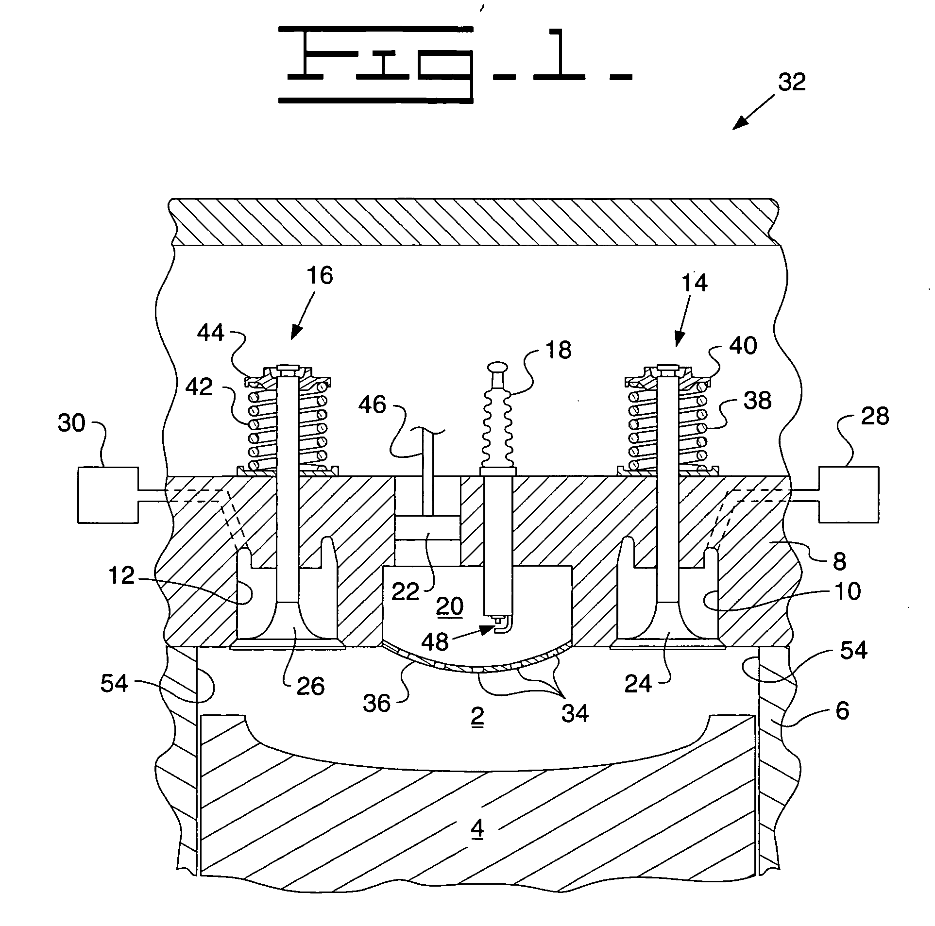
[0021] Referring to FIG. 1, a portion of an exemplary internal combustion engine 32 is provided. The internal combustion engine 32 includes an engine block 6 defining at least one cylinder 54, the number of which varies depending on engine 32. For example, a 4-cylinder engine 32 would include four cylinders 54. It should be appreciated that engine 32 may be any type of spark-ignited internal combustion engine, such as a gasoline or natural gas engine.

[0022] Internal combustion engine 32 also includes an intake manifold 30 and an exhaust manifold 28. Intake manifold 30 provides fluid, such as an air or air / fuel mixture, to a main combustion chamber 2, which is partially defined within cylinder 54.

[0023] Internal combustion eng...


PUM


Abstract

An internal combustion engine and method of operating an engine is provided. The engine comprises a piston cylinder formed within an engine block, an engine head secured to the engine block, a primary piston configured to slide within the piston cylinder, a main combustion chamber that is defined by the primary piston, piston cylinder, and engine head, a variable volume prechamber formed within the engine head and in fluid communication with the main combustion chamber, an ignition device configured to ignite a fuel within the prechamber, and a prechamber piston configured to translate within the prechamber. Translation of the prechamber piston within the prechamber varies the volume within the prechamber. The engine is characterized in that the prechamber comprises at least one orifice that provides fluid communication between the prechamber and the main combustion chamber.

Description

TECHNICAL FIELD [0001] The present invention relates generally to an internal combustion engine having a variable volume prechamber. BACKGROUND [0002] Internal combustion engines often emit harmful oxides of nitrogen (“NOx”) during operation. These oxides form when nitrogen and oxygen, both of which are present in the air used for combustion, combine within the main combustion chambers. Typically, the level of NOx formed increases as the peak combustion temperatures within the combustion chambers increase. As such, minimizing the peak combustion temperatures within the main combustion chambers generally reduces the emission of NOx. [0003] For this reason, leaner gas or leaner gaseous fuel mixtures are used for reducing the peak combustion temperatures in the main combustion chambers, thus reducing the amount of harmful NOx emitted. A lean gas or gaseous fuel mixture has a relatively large air-to-fuel ratio when compared to a gas mixture having a stoichiometric air-to-fuel ratio. Acc...

Claims


Application Information

Patent Timeline
Patent Type & Authority Applications(United States)
IPC IPC(8): F02B19/10
CPCF02B19/06Y02T10/125F02D15/04F02B19/12Y02T10/12
Inventor BAILEY, BRETTFIVELAND, SCOTTGONG, WEIDONG
Owner CATERPILLAR INC
Why Eureka
Try Eureka