Overhead baggage rack unit of railway car

a baggage rack and railway car technology, applied in the direction of axle-box lubrication, railway bodies, packaging, etc., can solve the problems of neither cost-effective nor light weight, and achieve the effect of cost-effectiveness and light weigh

Inactive Publication Date: 2006-10-05
HITACHI LTD
View PDF9 Cites 3 Cited by
  • Summary
  • Abstract
  • Description
  • Claims
  • Application Information

AI Technical Summary

Benefits of technology

[0010] Therefore, the object of the present invention is to provide a light weight, cost-effective overhead baggage rack body.

Problems solved by technology

Moreover, the overhead baggage rack is required to be light weight and cost effective, but the prior art overhead baggage rack was formed of metal plates and nets, which were neither light weight nor cost effective.

Method used


Image

  • Overhead baggage rack unit of railway car
  • Overhead baggage rack unit of railway car
  • Overhead baggage rack unit of railway car

Examples


Embodiment Construction

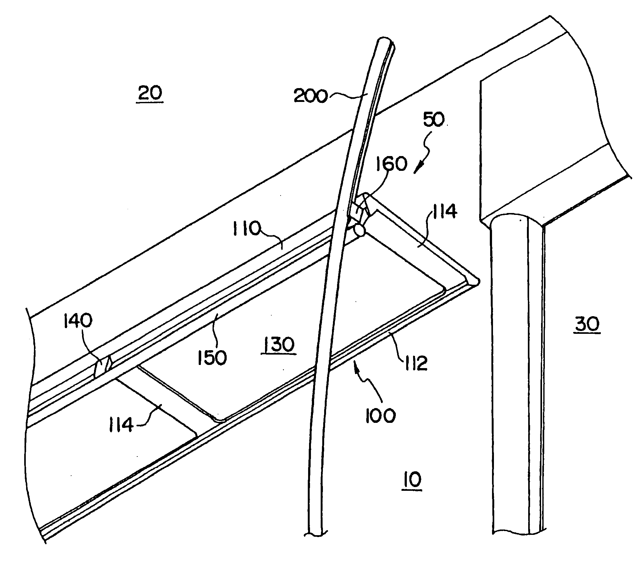
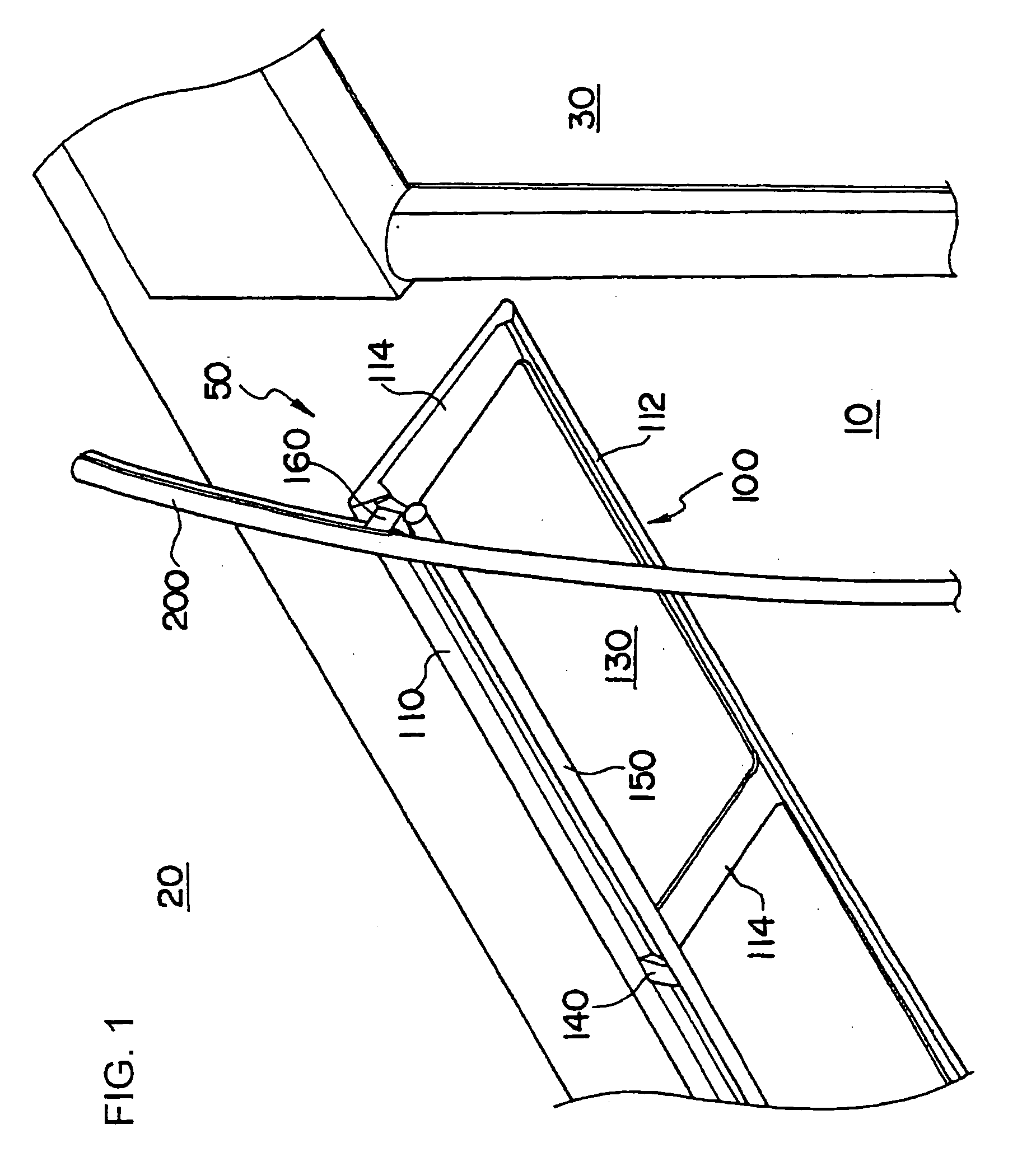
[0022]FIG. 1 is a perspective view showing the general structure of an overhead baggage rack unit according to the present invention.

[0023] A railway car is composed of an underframe not shown for supporting a floor of the car, side frames 10, a roof frame 20 and so on. Interior panels are mounted on the inner sides of the side frames 10 and the roof frame. Doors 30 for entering and exiting the car and windows are disposed on the side frame 10.

[0024] The overhead baggage rack unit denoted as a whole by reference number 50 includes an overhead baggage rack body 100 and a pole 200 for supporting the overhead baggage rack body 100. The overhead baggage rack body 100 is connected to the pole 200 via a bracket portion 160 described in detail later.

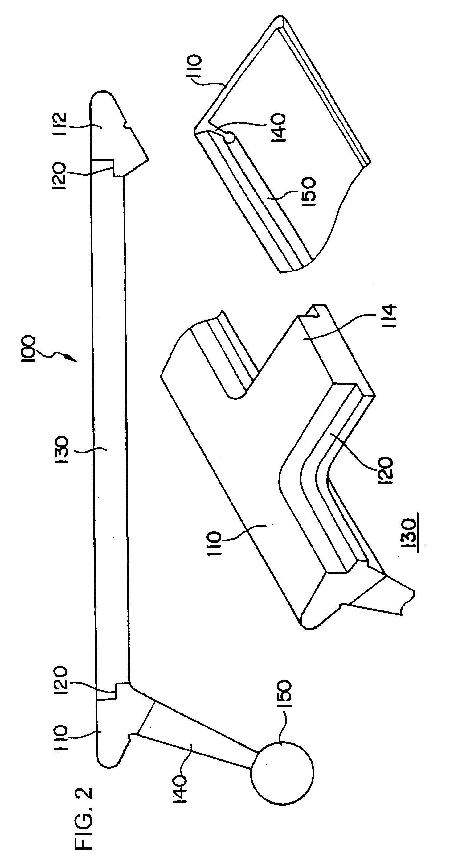
[0025]FIG. 2 illustrates the details of the overhead baggage rack body 100.

[0026] The overhead baggage rack body 100 has an integrated structure formed by extruding aluminum alloy, in which the finished product is formed by cutting unnecess...


PUM


Abstract

The invention provides an improved overhead baggage rack for a railway car. An overhead baggage rack unit 50 provided at a shoulder portion between a side frame 10 and a roof frame 20 of a railway car comprises an overhead baggage rack body 100 and a pole 200. The overhead baggage rack body 100 comprises a front edge portion 110, a rear edge portion 112 and a transverse member 114 formed by mechanically cutting out portions from an extruded aluminum alloy member, and thereby, an opening 130 is formed to which an overhead baggage rack panel is attached. A grip bar 150 is cut and formed to an area lower than the front edge portion 110. The front edge portion 110 is fixed via a bracket 160 to the pole 200.

Description

[0001] The present application is based on and claims priority of Japanese patent application No. 2005-78153 filed on Mar. 17, 2005, the entire contents of which are hereby incorporated by reference. BACKGROUND OF THE INVENTION [0002] 1. Field of the Invention [0003] The present invention relates to an overhead baggage rack unit provided on a railway car or the like (such as a train or a monorail car). [0004] 2. Description of the Related Art [0005] The railway car is composed of an underframe constituting a floor member of the car, a side frame, a roof frame and so on. [0006] In a commuter train and the like, a long sheet is disposed along the longitudinal direction of the vehicle, and an overhead baggage rack is provided at the overhead area of the long sheet. [0007] As disclosed in Japanese Patent Application Laid-Open Publication No. 11-222125 (patent document 1), luggages of passengers are placed on the overhead baggage rack, but according to the prior art car structure, the ov...

Claims


Application Information

Patent Timeline
Patent Type & Authority Applications(United States)
IPC IPC(8): B65D88/00
CPCB61D37/003B61D17/00
Inventor TODORI, SEIJIROTANII, YASUNORINISHIYAMA, KANJIHIROSE, SHINGO
Owner HITACHI LTD
Why Eureka
Try Eureka