Photomultiplier

a technology of photomultiplier and focusing electrode, which is applied in the field of photomultiplier, can solve the problems of difficult shortening the production time, requiring experience for the worker, and affecting so as to and improve the efficiency of the electron-multiplying unit. dramatic

Inactive Publication Date: 2006-10-05
HAMAMATSU PHOTONICS KK
View PDF12 Cites 0 Cited by
  • Summary
  • Abstract
  • Description
  • Claims
  • Application Information

AI Technical Summary

Benefits of technology

The patent describes a photomultiplier with a simplified structure that allows for easy alignment and assembly of the accelerating electrode and dynode unit. This is achieved by providing protruding portions on the insulating support members that serve as a reference for positioning the accelerating electrode. By fixing the accelerating electrode to the insulating support members, the need for precise alignment and specialized fixing tools is eliminated, resulting in improved productivity and reduced performance variations between produced photomultipliers.

Problems solved by technology

The patent text discusses the development of a new PET (Positron-Emission Tomography) apparatus called TOF-PET, which uses a special technique called time-of-flight (TOF) to create vivid images of the body. The text describes the use of a photomultiplier with a large capacity and high-speed response for the detectors in the apparatus. The technical problem addressed in the text is how to improve the performance of the photomultiplier to ensure accurate and reliable detection of gamma rays in the TOF-PET apparatus.

Method used


Image

  • Photomultiplier
  • Photomultiplier
  • Photomultiplier

Examples


Embodiment Construction

[0030] In the following, embodiments of a photomultiplier according to the present invention will be explained in detail with reference to FIGS. 1 to 11. In the explanation of the drawings, constituents identical to each other will be referred to with numerals identical to each other without repeating their overlapping descriptions.

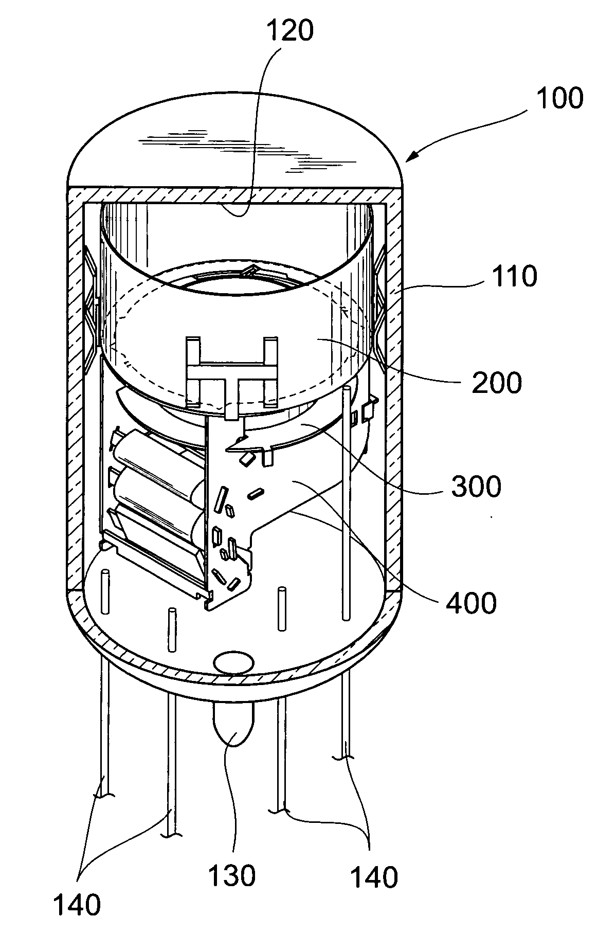
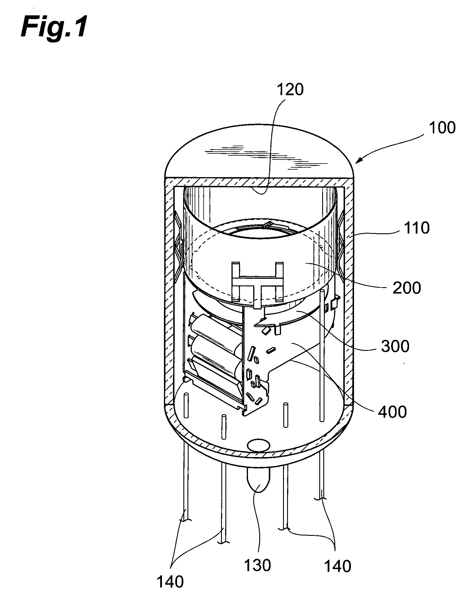
[0031]FIG. 1 is a partially cutaway view illustrating a schematic structure of a photomultiplier of an embodiment according to the present invention.

[0032] As shown in FIG. 1, a photomultiplier 100 includes a sealed container 110 provided with a pipe 130 (solidified after evacuation) for evacuating the inside at the bottom thereof, a cathode 120 provided in the sealed container 110 and an electron-multiplying unit.

[0033] The sealed container 110 is constituted by a cylindrical body having a face plate, the inside of which is formed with a cathode 120, and a stem supporting a plurality of lead pins 140 in their penetrating state. The electron-multiplyin...


PUM


Abstract

The present invention relates to a photomultiplier having a structure for performing a high gain and achieving a higher productivity in a state keeping or improving an excellent high-speed response. In the photomultiplier, an electron-multiplying unit accommodated in a sealed container has a structure that enables an integrated assembly of a focusing electrode, an accelerating electrode, a dynode unit, and an anode. Specifically, the accelerating electrode composes a lower electrode and an upper electrode fixed each other by welding at a plurality of spots. The lower electrode is held at a pair of insulating support members in a state for the pair of insulating support members to grasp unitedly it together with the dynode unit and anode. Additionally, the upper electrode has one or more slit grooves for pinching a part of the pair of insulating support members. With this construction, the accelerating electrode constituted by the lower electrode and upper electrode is fixed at the pair of insulating support members in a state to be aligned with high accuracy by using the pair of insulating support members as a reference member.

Description


Claims


Application Information

Patent Timeline
Owner HAMAMATSU PHOTONICS KK
Why Eureka
Try Eureka