Printing apparatus and control method

a control method and printing apparatus technology, applied in the field of printing apparatus, can solve the problems of increasing the cost of data saving, reducing the efficiency of data saving, and limited changeable job properties

Inactive Publication Date: 2006-10-05
CANON KK
View PDF5 Cites 87 Cited by
  • Summary
  • Abstract
  • Description
  • Claims
  • Application Information

AI Technical Summary

Benefits of technology

[0009] In one aspect of the present invention, a printing apparatus includes an input unit configured to input a job containing image data and property information of the image data, a first memory configured to store the job input by the input unit, an image processing unit configured to process the image data of the job in accordance with the property information of the input job, a second memory configured to store the job processed by the image processing unit, an output unit configured to output the job in accordance with the property information of the processed job, a setting unit configured to set saving of the input job in the first memory and saving of the processed job in the second memory, and a control unit configured to control saving of the input job and the processed job in accordance with a saving method set by the setting unit and, in outputting the saved job, indicating an enable / disable state of change of the property information in accordance with the saving method and receiving change of the property information.
[0010] The above and other objects and features of the present invention will appear more fully hereinafter from a consideration of the following description taken in connection with the accompanying drawing wherein one example is illustrated by way of example.

Problems solved by technology

However, changeable job properties are limited to, e.g., the number of copies and the post processing function.
On the other hand, in data before RIP (e.g., PDL data described in a page description language (PDL)), any job property can be changed, though RIP is time-consuming.
However, when a number of large job data are saved, a hard disk with a large capacity or a large number of hard disks are necessary, resulting in an increase in cost for data saving.

Method used


Image

  • Printing apparatus and control method
  • Printing apparatus and control method
  • Printing apparatus and control method

Examples


first embodiment

[Configuration of Digital Print System]

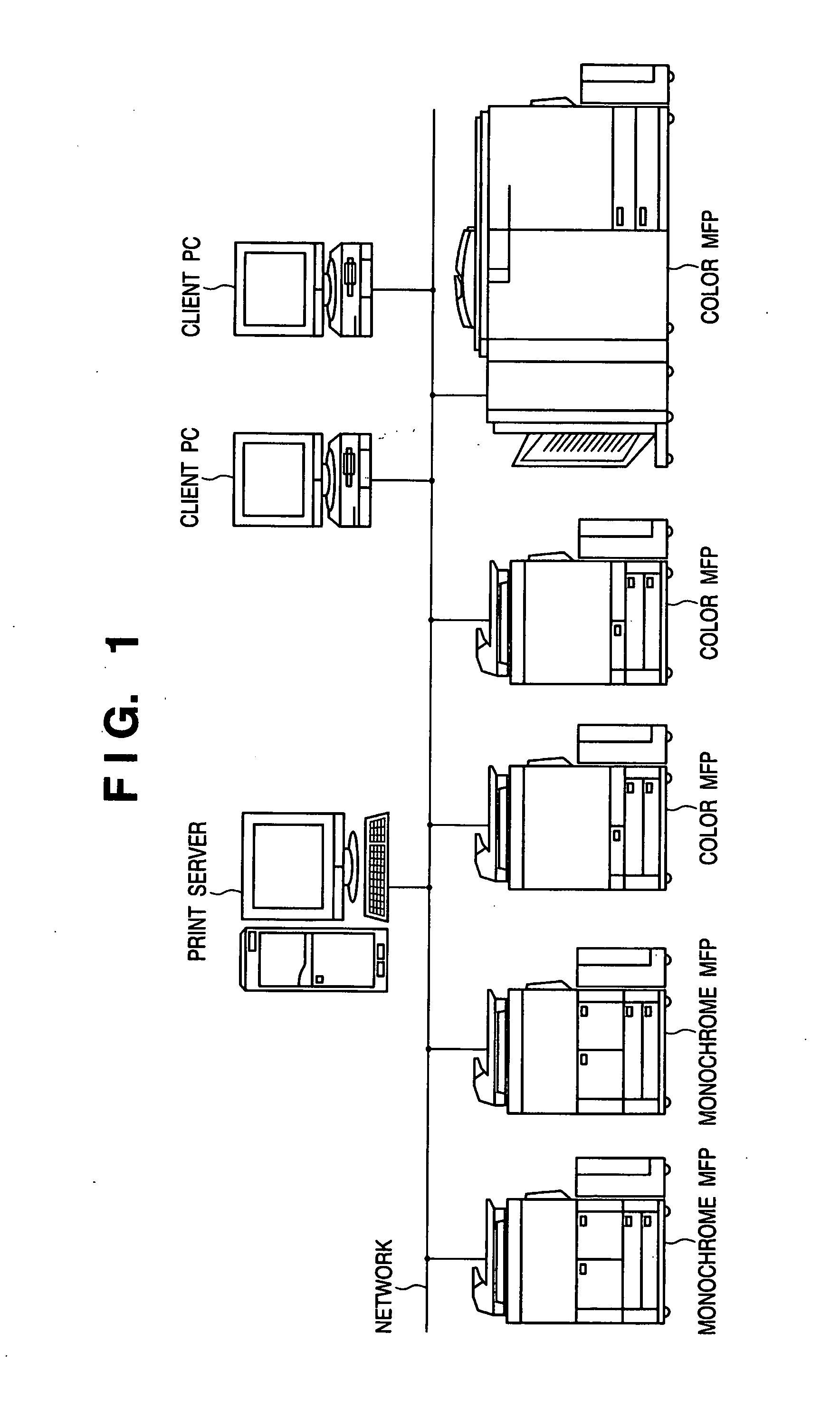
[0067]FIG. 1 is a view showing a configuration example of a digital print system.

[0068] In the digital print system (to be simply referred to as a “system” hereinafter), one or a plurality of print servers 2, client PCs 3, monochrome MFPs 4, and color MFPs 5 and 6 are connected to a network such as a local area network (LAN).

[0069] The print server 2 has two roles. The first role is information transmission / reception to / from the outside of the system. Image information or setting information of a job to be input to the system is input to the print server 2 first. When the job is ended, the print server 2 notifies the outside of the system of information of, e.g., the status.

[0070] The second role of the print server 2 is management control in the system. The print server 2 collectively manages jobs input from the outside and those generated in the system and monitors the conditions of all devices and all jobs in the system. Suspension, sett...

second embodiment

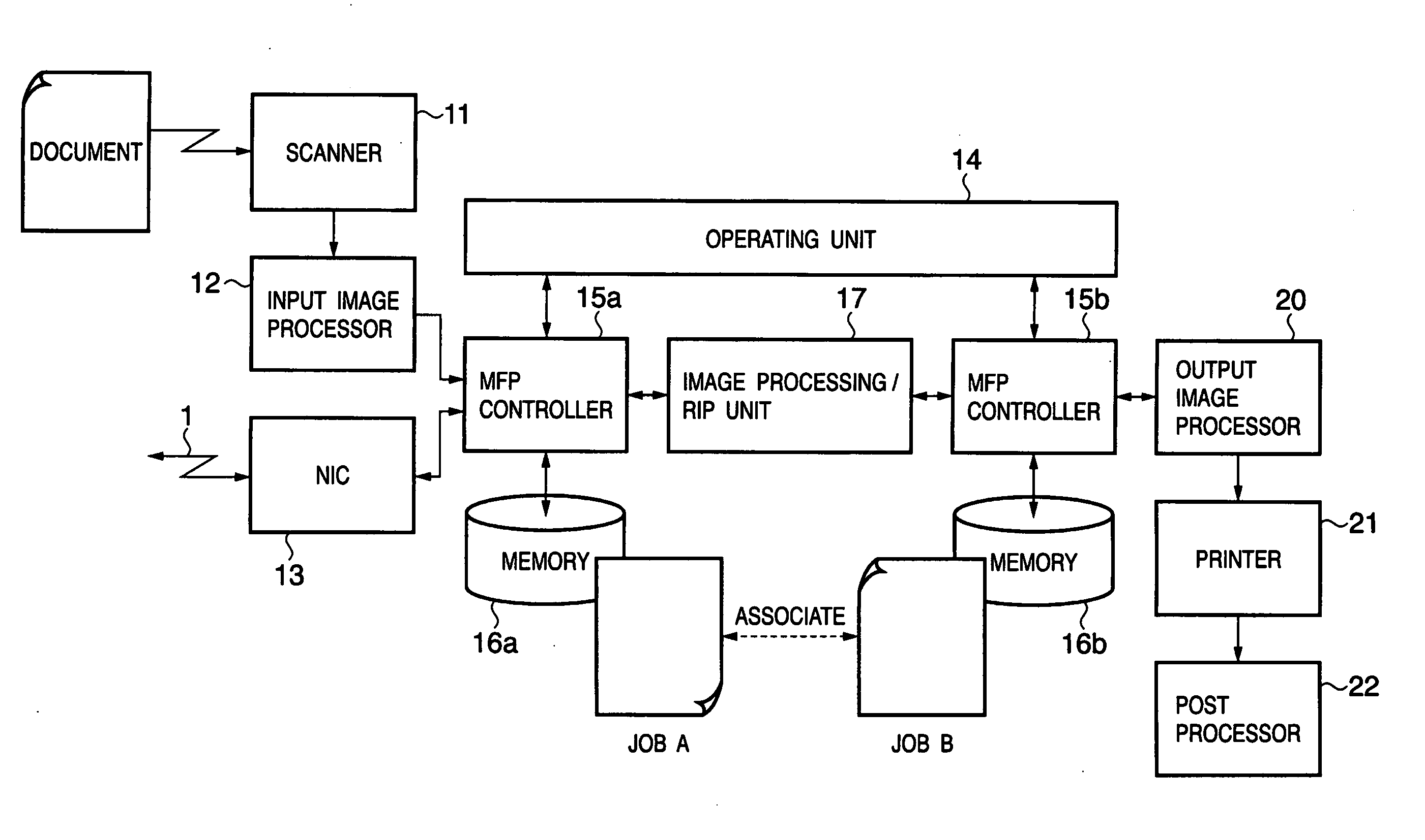
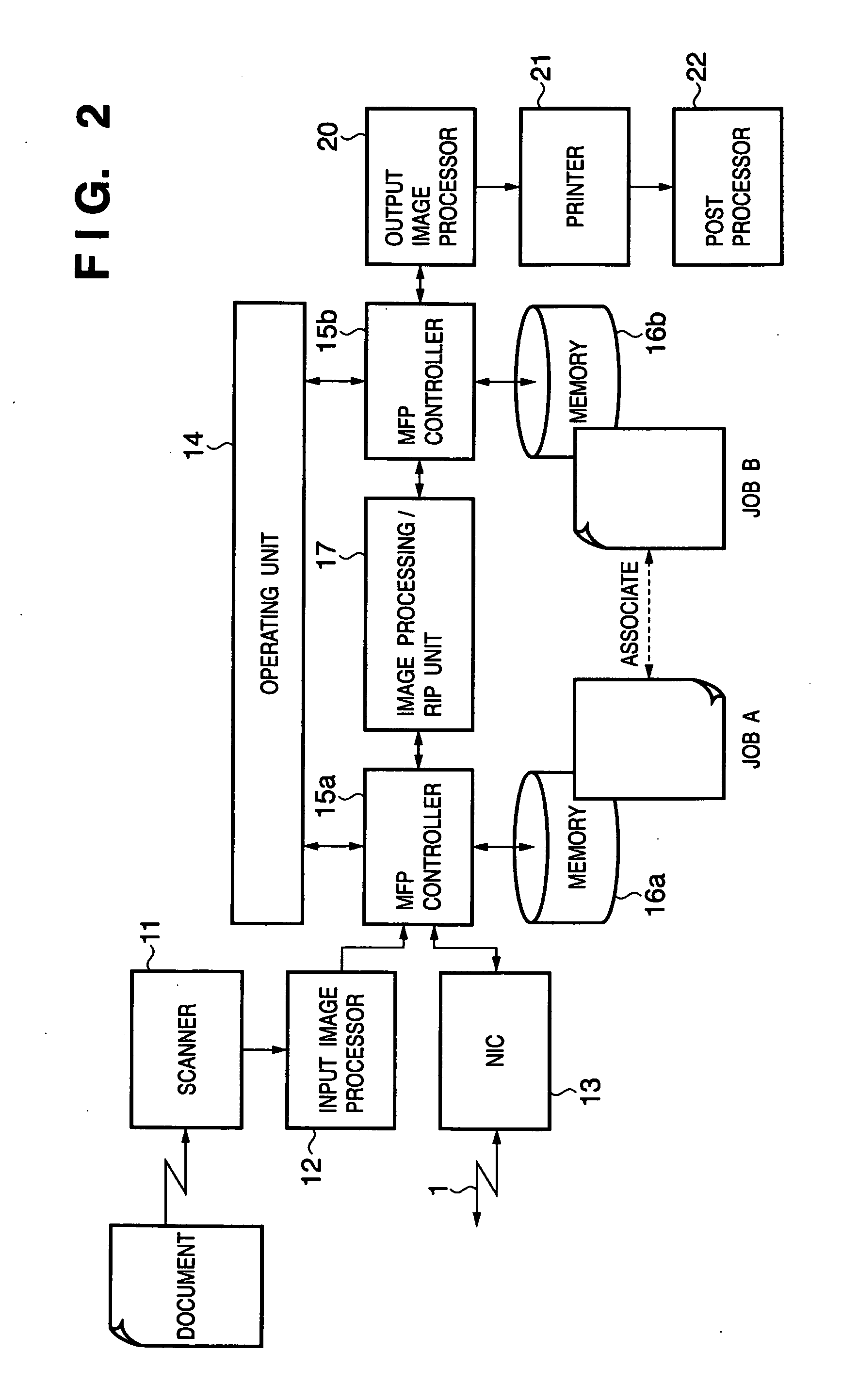
[0267] Image processing according to the second embodiment of the present invention will be described below. The same reference numerals as in the first embodiment denote essentially the same components in the second embodiment, and a detailed description thereof will be omitted.

[0268] In the first embodiment, a job of PDL data received from the network 1 is re-printed. In the second embodiment, an example wherein a job of a scan image is reprinted will be described.

[0269]FIG. 37 is a view showing an example of a box scan setting window. This window is displayed by pressing a “Read Document” button in the user box window shown in FIG. 31. FIG. 39 is a flowchart showing an example of box scan processing. This processing is executed by an MFP controller.

[0270] The user sets; e.g., the scaling factor and reading size in scanning and the double-sided document or single-sided document, inputs a document name as needed, and presses a start key shown in FIG. 11. If no document name is i...

third embodiment

[0282] Image processing according to the third embodiment of the present invention will be described below. The same reference numerals as in the first and second embodiments denote essentially the same components in the third embodiment, and a detailed description thereof will be omitted.

[0283] In the first and second embodiments, “(1) Place Importance on Print Start Speed”, “(2) Place Importance on Print Setting Flexibility”, or “(3) Place Importance on Both” is selected for each job as a job saving method. However, considering a case to repeatedly use the same saving method, the operability can be improved by selecting one of the saving methods in advance as default setting.

[0284] When a user mode key shown in FIG. 11 is pressed, an MFP controller displays a user mode window shown in FIG. 47 on an operating unit 14. The user can set same setting conditions for all jobs in advance by the user mode window. When a “Set Common Specifications” button is pressed, the MFP controller d...


PUM


Abstract

An image processing apparatus is provided. An input image processor or NIC inputs a job containing image data and property information of the image data. An MFP controller stores the input job in a first memory. An image processing/RIP unit processes the image data in accordance with the property information. The MFP controller stores the job processed by the image processing/RIP unit in a second memory. An output image processor outputs the job in accordance with the property information. The MFP controller sets saving of the jobs in the first and second memories and, in outputting the saved job, indicates an enable/disable state of change of the property information in accordance with the saving method and receives change of the property information.

Description

FIELD OF THE INVENTION [0001] The present invention relates to a printing apparatus and a control method thereof and, more particularly, to, e.g., processing of inputting a job having image data and its property information, processing the image data in accordance with the property information, and outputting the job in accordance with the property information. BACKGROUND OF THE INVENTION [0002] When image data from a computer is printed or copied by an image forming apparatus (or MFP: Multi Functional Peripheral) in an office environment, the printing is often executed only once. Even when the image to be printed is saved in the internal memory or hard disk of the apparatus, the data is erased immediately. [0003] If a user uses a function (so-called box function) of intentionally saving, in a memory, raster data which has undergone raster image processing (RIP) to print an image later, printing can be done after changing some limited settings such as the number of copies and the po...

Claims


Application Information

Patent Timeline
Patent Type & Authority Applications(United States)
IPC IPC(8): G06F3/12
CPCH04N1/00432H04N1/00472H04N1/00474H04N2201/3274H04N1/32358H04N2201/0094H04N2201/3242H04N1/00482
Inventor TAKAHASHI, HIROYUKI
Owner CANON KK
Why Eureka
Try Eureka