

Expanded beam converter for mil-prf-83526/17 optical connector
a fiber optic connector and converter technology, applied in the field of fiber optic connector converters, can solve problems such as system failure, and achieve the effects of less sensitive to contamination, improved operating characteristics, and less added time or expens
- Summary
- Abstract
- Description
- Claims
- Application Information
AI Technical Summary
Benefits of technology
Problems solved by technology
Method used
Image

Examples
Embodiment Construction
[0015] Referring now to the drawings, wherein like reference numerals designate identical or corresponding parts throughout the several views, and more particularly to FIGS. 3-5 thereof, an embodiment of the present invention is a device or fiber optic bulkhead connector 50 which is displayed therein.
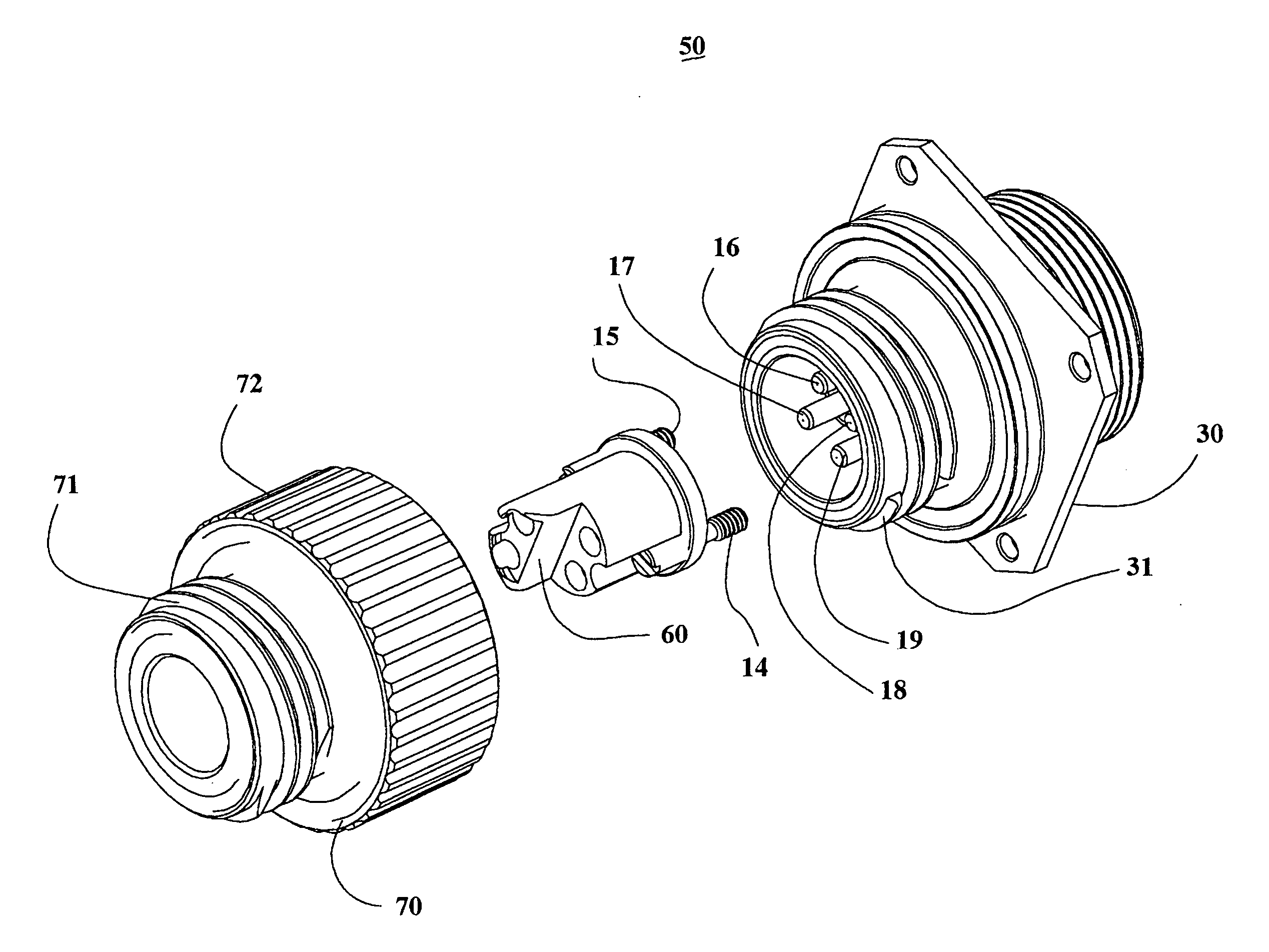
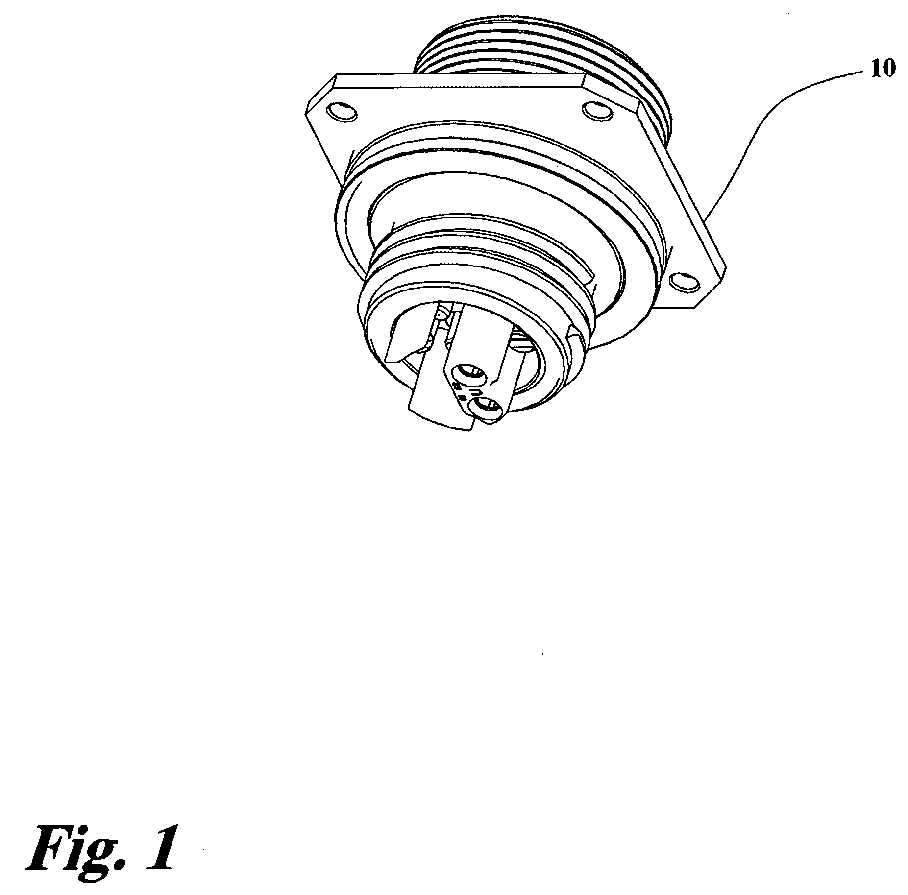
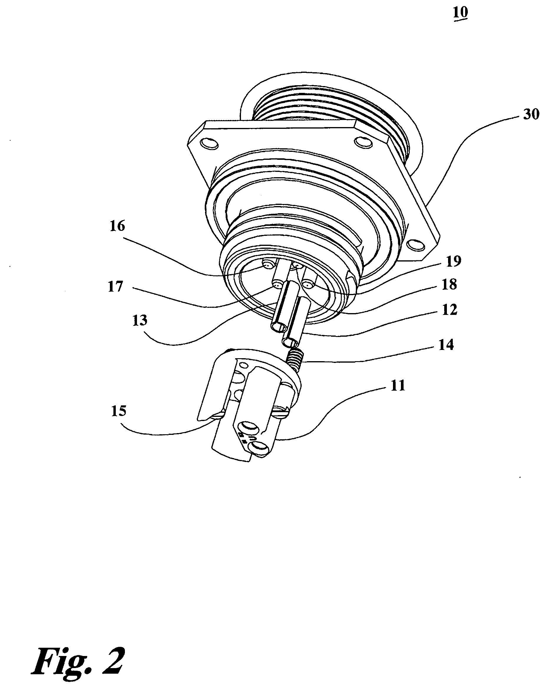
[0016]FIG. 1 is a perspective view of the prior art fiber optic bulkhead connector 10. FIG. 2 is an exploded perspective view of the prior art fiber optic bulkhead connector 10. The fiber optic bulkhead connectors 10 of the prior art utilize a well accepted part, the bulkhead connector housing 30, as one element of the invention. However, as previously described, the prior art fiber optic bulkhead connector 10 has disadvantages. As shown in FIG. 2, the disadvantageous parts, such as the insert body or cap 11 and the alignment sleeves 12 and 13, are removed. The parts are removed by unscrewing screws 14, and 15 from the bulkhead connector housing 30 so as to be able to remove the cap 11...
PUM
 Abstract
Description
Claims
Application Information