Autonomously movable agricultural vehicle

a technology of autonomous movement and agricultural vehicles, applied in the direction of process and machine control, distance measurement, instruments, etc., can solve the problems of limiting the effectiveness of autonomously moving agricultural vehicles, the time of agricultural vehicles, etc., and achieves less energy loss, less contamination, and less likelihood of optical sensors not working properly due to dirt.

Inactive Publication Date: 2012-09-06
LELY PATENT
View PDF4 Cites 5 Cited by
  • Summary
  • Abstract
  • Description
  • Claims
  • Application Information

AI Technical Summary

Benefits of technology

[0032]In one embodiment of the autonomously movable agricultural vehicle, the autonomously movable agricultural vehicle comprises an ultrasound sensor and / or an optical sensor to recognize obstacles. An optical sensor could be a camera which is mounted on the autonomously movable agricultural vehicle and with which the obstacles can be recognized. The advantage of optical sensors is that they are relatively inexpensive and that image processing can possibly be carried out on the recorded images in order to collect additional information relating to an obstacle. A disadvantage of optical sensors is that agricultural vehicles do not always operate in a clean environment, so that the likelihood of an optical sensor not functioning properly due to dirt is relatively high. As a result, an optical sensor could supply incorrect information to the control circuit. An ultrasound sensor is somewhat less sensitive to contamination, but is somewhat more expensive. The control circuit is, for example, configured to add obstacles in the route to the storage medium if new obstacles are identified by the ultrasound sensor and / or the optical sensor.
[0033]In one embodiment of the autonomously movable agricultural vehicle, the control circuit is configured to approach an obstacle in the route in a predefined manner. If the position of an obstacle is known, the obstacle could, for example, be approached at reduced speed, so that the autonomously movable agricultural vehicle is not damaged by the collision. A collision at a lower speed also causes less energy loss than a high-speed collision.

Problems solved by technology

A disadvantage of the autonomously movable agricultural vehicles described above is that the charging time of the agricultural vehicles limits the effectiveness of the autonomously movable agricultural vehicle.

Method used


Image

  • Autonomously movable agricultural vehicle
  • Autonomously movable agricultural vehicle
  • Autonomously movable agricultural vehicle

Examples


Embodiment Construction

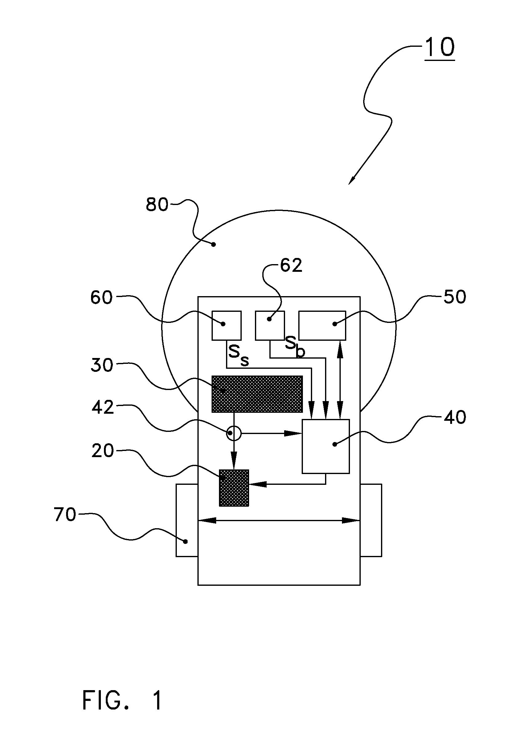
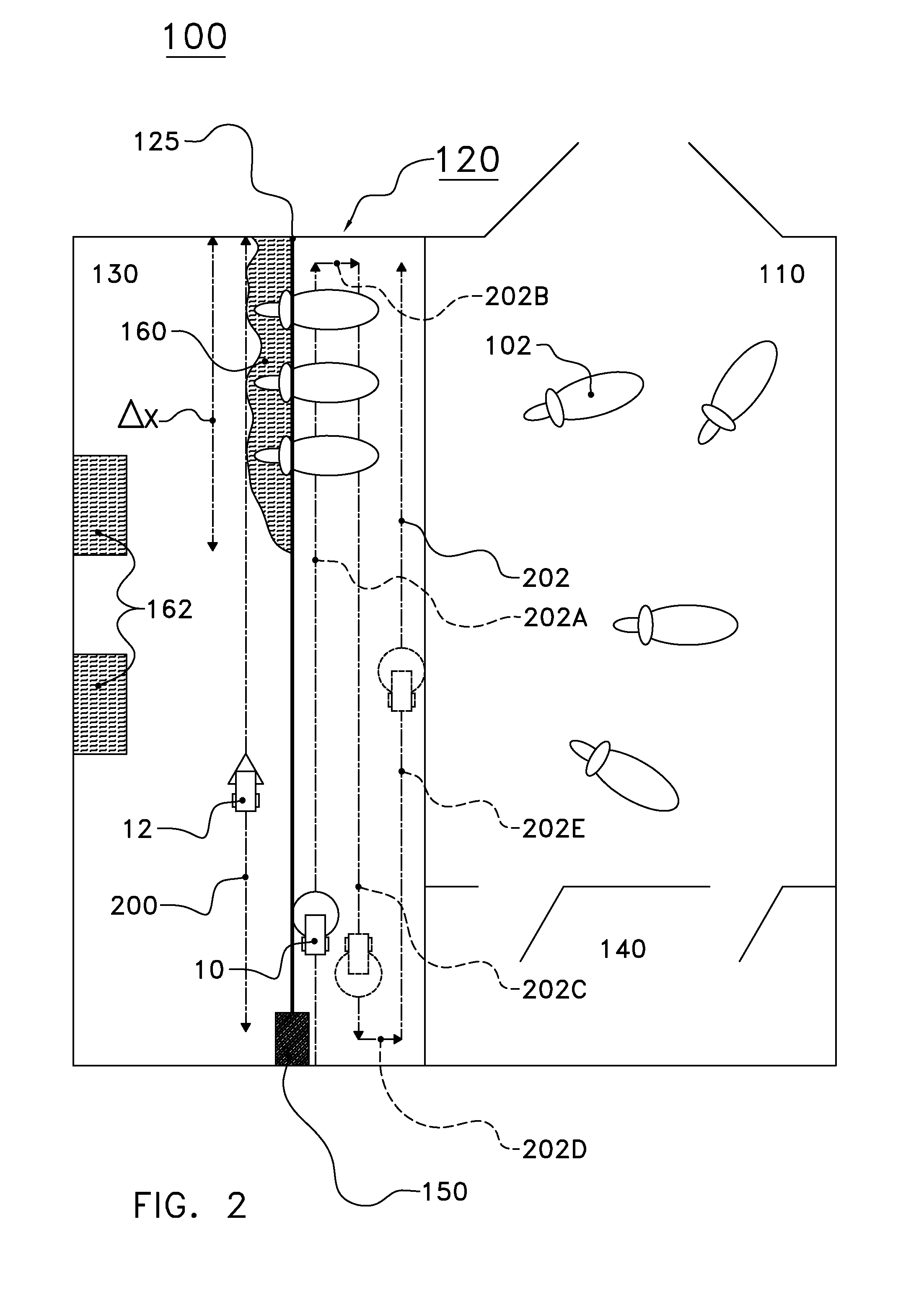
[0039]The following is a description of certain embodiments of the invention, given by way of example only and with reference to the drawings. FIG. 1 shows a schematic top view of an autonomously movable vehicle 10 for agricultural applications according to the invention. The autonomously movable vehicle 10 for agricultural applications comprises a motor 20 to drive the autonomously movable agricultural vehicle 10 and a battery 30 to supply energy to the motor 20. The autonomously movable agricultural vehicle 10 also comprises a control circuit 40 to drive the motor 20 and to adjust a speed of the autonomously movable agricultural vehicle 10. The control circuit 40 is configured here to set the speed vA, vB, . . . (see FIG. 3) of the autonomously movable agricultural vehicle 10 in such a way that the energy EA, EB, . . . (see FIG. 3) drawn from the battery 30 over a predefined distance Δx (see FIG. 2) is minimal. The energy available in the battery 30 is thereby used to optimum effe...


PUM


Abstract

An autonomously movable agricultural vehicle for agricultural applications, a method for controlling the autonomously movable agricultural vehicle, and software for managing the autonomously movable agricultural vehicle. The autonomously movable agricultural vehicle includes a motor to drive the vehicle and a battery to supply energy to the motor. The autonomously movable agricultural vehicle also includes a control circuit to control the motor to adjust the speed of the vehicle, wherein the control circuit is configured to set the speed of the vehicle, wherein energy drawn from the battery over a predefined distance is minimal.

Description

CROSS REFERENCE TO RELATED APPLICATIONS[0001]This application is a continuation of PCT application number PCT / NL2010 / 000160 filed on 3 Nov. 2010, which claims priority from Netherlands application number 1037476 filed on 17 Nov. 2009. Both applications are hereby incorporated by reference in their entireties.BACKGROUND OF THE INVENTION[0002]1. Field of the Invention[0003]The invention relates to an autonomously movable agricultural vehicle. The invention also relates to a method for controlling an autonomously movable agricultural vehicle and software for managing an autonomously movable agricultural vehicle.[0004]2. Description of the Related Art[0005]Autonomously movable agricultural vehicles are increasingly used in agriculture. Autonomously movable agricultural vehicles of this type are, for example, used to clean livestock buildings or, for example, to transport feed, ensuring that fresh feed is continuously available to animals in a livestock building. Autonomously movable agr...

Claims


Application Information

Patent Timeline
Patent Type & Authority Applications(United States)
IPC IPC(8): G05D1/02
CPCG05D2201/0201G05D1/0217
Inventor NOORDAM, JACCO
Owner LELY PATENT
Why Eureka
Try Eureka