Medical device having integral traces and formed electrodes

a medical device and integral trace technology, applied in the field of medical devices, can solve the problems of difficult connection of the difficulty of attaching wires to the appropriate connector pins of medical devices, and the difficulty of identifying the problems identified above,

Active Publication Date: 2007-06-12
ST JUDE MEDICAL ATRIAL FIBRILLATION DIV
View PDF128 Cites 166 Cited by
  • Summary
  • Abstract
  • Description
  • Claims
  • Application Information

AI Technical Summary

Benefits of technology

[0011]Generally, one embodiment of the present invention takes the form of a catheter having electrically conductive traces and external electrical contacts. Each trace may be in electrical connection with one or more external electrical contacts. More specifically, each trace is typically electrically connected to a single contact. The traces and contacts may assist in diagnosis and / or detection of bio-electrical signals emitted by organs, and may transmit such signals to a connector or diagnostic device affixed to the catheter.
[0014]In yet another embodiment of the present invention, a medical device may be provided with one or more arbitrarily-shaped electrodes on its surface, for example at the device tip. These arbitrarily-shaped electrodes operate in either a diagnostic or energy-delivering mode, as necessary. The arbitrarily-shaped electrodes may obtain improved information on electrical signal directional propagation when recording tissue responses to electrical energy, and may also improve accuracy when ablating tissue.

Problems solved by technology

At the catheter's proximal end, these wires often simply terminate with little or no identification separating one wire from the next, making attaching a wire to the appropriate connector pin of a medical device difficult.
Apparatus leads often suffer from similar problems.
In any of these energy-delivery applications, however, the problems identified above typically still exist.

Method used


Image

  • Medical device having integral traces and formed electrodes
  • Medical device having integral traces and formed electrodes
  • Medical device having integral traces and formed electrodes

Examples


embodiment 600

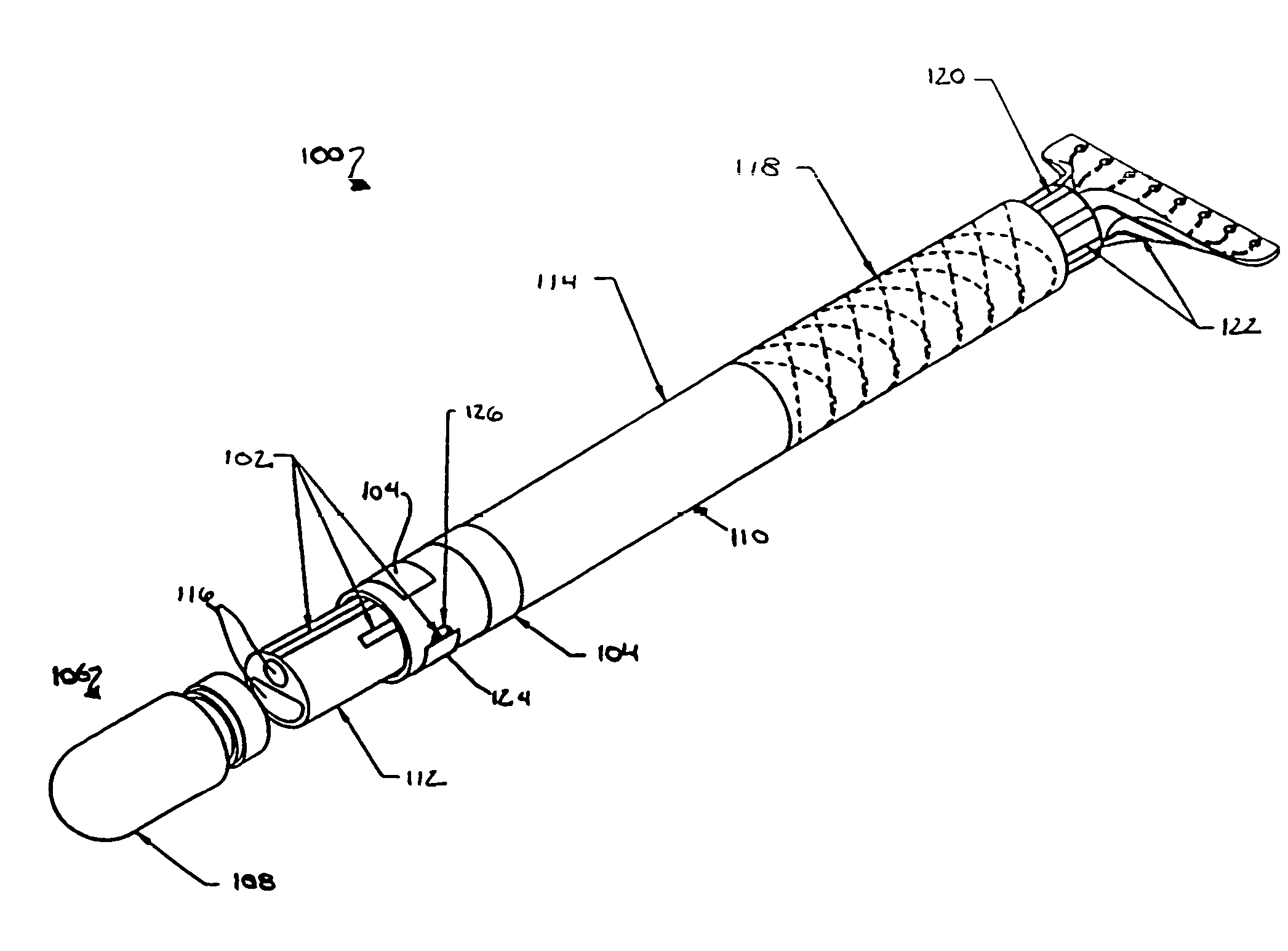
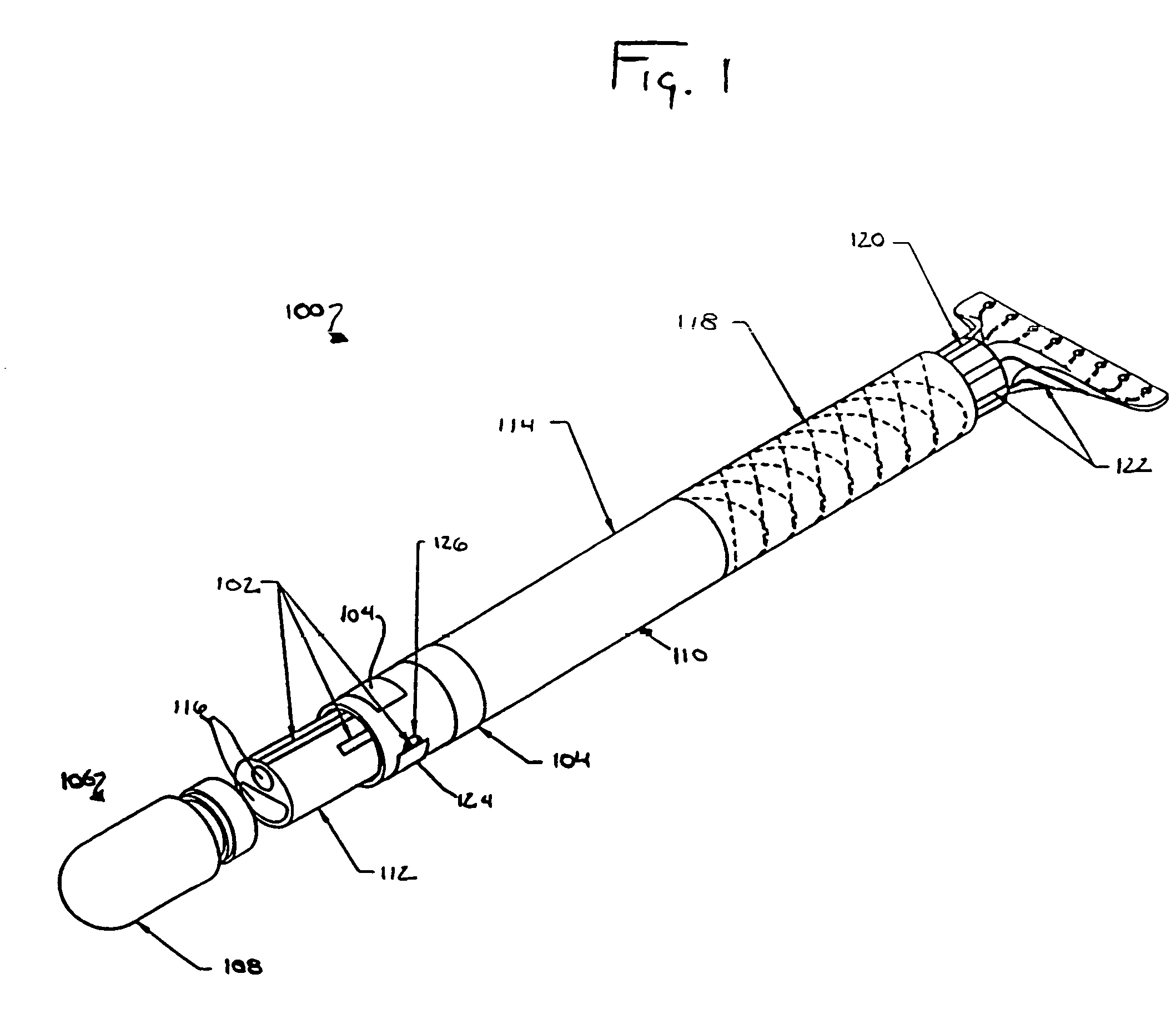
[0086]As with the embodiment of FIG. 4, the outer jacket 114 of the present embodiment 600 may be made of multiple outer jacket segments 404, 406. These segments may be bonded to one another, or may each be bonded to the layer directly beneath them. Further, braided material 118 may be included in an outer jacket segment 406.

[0087]Similar to the single-tube catheter 100 discussed with reference to FIGS. 1 through 4, the present embodiment 600 includes a shoulder configuration 606. Part of this shoulder 606 is formed by a first inner layer 608, which abuts the first tube. Here, however, a second inner layer 610 forms a second portion of the shoulder 606 for contact with the inner tube 604 defining the lumen 116. This second shoulder portion is optional, but may provide additional security with respect to properly seating a tube. Further, the second shoulder assists in properly aligning any inner tube traces 102d within the catheter assembly.

[0088]FIG. 9 depicts a cross-sectional view...

embodiment 500

[0090]FIG. 10 depicts an isometric view of the adapter 900 mentioned in the discussion of FIGS. 6–9. Generally, this adapter embodiment differs from the embodiment 500 shown in FIGS. 1–5 in that it includes dual layers of longitudinally aligned adapter traces 122a, 122b. The mating of the adapter 900 with the catheter 600 was previously discussed with respect to FIGS. 1, 5, and 9. The adapter 900 is shown with an outer jacket 500.

[0091]Typically, the adapter outer jacket 500 is formed from a nonconductive material that may or may not be identical to the material used to form the catheter shaft 110. The adapter traces 122a, 122b may be exposed on the plug portion 1000 of the adapter (i.e., the portion of the adapter fitting within the catheter). Typically, these traces are concealed within the nonconductive catheter shaft 110 once the adapter 900 is mated with the catheter 600. Further, the traces 122a, 122b are generally embedded within the nonconductive material of the adapter jack...

embodiment 900

[0093]FIG. 11 depicts an alternative embodiment of an adapter 1100. In this embodiment, the adapter 1100 lacks the planar structure, or fan tail 1002, of the embodiment 900 shown in FIG. 10. Instead, the adapter traces 122 terminate in conductive prongs 1102 extending rearwardly from the adapter. Further, unlike the adapter 900 of FIG. 10, the present adapter 1100 has a reverse stair-step configuration 1104 at the end designed to mate with the catheter. Accordingly, rather than inserting a portion of the adapter into a catheter 100, the catheter is at least partially inserted into the adapter. This requires the distal end of the catheter 100 to have a mating stair-step protrusion. The shoulder 1104 inside the adapter 1100 longitudinally aligns the catheter with the adapter. It should be noted that either type of adapter (one having a fan tail or cylindrical prong arrangement) may be used with either catheter mating configuration.

[0094]FIG. 12 depicts the adapter 1100 of FIG. 11, as ...


PUM


Abstract

A catheter or lead having electrically conductive traces and external electrical contacts. Each trace may be in electrical connection with one or more external electrical contacts. More specifically, each trace is typically electrically connected to a single contact. The traces and contacts may assist in diagnosis and / or detection of bio-electrical signals emitted by organs, and may transmit such signals to a connector or diagnostic device affixed to the catheter. The external electrical contacts may detect bioelectric energy or may deliver electrical energy to a target site.

Description

[0001]This application is related to U.S. patent application Ser. No. 10 / 668,831, filed Sep. 22, 2003, entitled “Method for Manufacturing Medical Device Having Embedded Traces and Formed Electrodes.”[0002]a. Field of the Invention[0003]The invention relates generally to the field of medical instruments, and more particularly to a medical instrument for introduction into a body and having arbitrarily-shaped electrically conductive surfaces formed thereon.[0004]b. Background Art[0005]Catheters have been in use for medical procedures for many years. Among other uses, catheters can be used for medical procedures to examine, diagnose, and / or treat tissue while positioned at a specific location within the body otherwise inaccessible without more invasive procedures. For example, one procedure (often referred to as “catheter ablation”) utilizes a catheter to convey electrical energy to a selected location within the human heart to necrotize cardiac tissue. This procedure is often colloquia...

Claims


Application Information

Patent Timeline
Patent Type & Authority Patents(United States)
IPC IPC(8): A61B18/18A61B18/04A61B5/042A61B18/14A61N1/05
CPCA61B5/0422A61B5/6852A61B18/1492A61N1/05A61B2018/00839A61B2562/227A61B5/287
Inventor JOHNSON, MICHAELHONOUR, KIRK S.
Owner ST JUDE MEDICAL ATRIAL FIBRILLATION DIV
Why Eureka
Try Eureka