Fault localization apparatus for optical line in wavelength division multiplexed passive optical network

a technology of fault localization and optical line, which is applied in the field of fault localization apparatus of optical line in wavelength division multiplexed passive optical network, can solve the problems of wdm pon, very serious effects, and decrease in network cost-effectiveness, and achieve the effect of efficient administration and improved network reliability

Inactive Publication Date: 2006-10-05
KOREA ADVANCED INST OF SCI & TECH
View PDF6 Cites 60 Cited by
  • Summary
  • Abstract
  • Description
  • Claims
  • Application Information

AI Technical Summary

Benefits of technology

[0012] Therefore, the present invention has been made in view of the above problems, and it is an object of the present invention to provide a fault localization apparatus for an optical line in a wavelength division multiplexed passive optical network (WDM PON), which is capable of being efficiently administrated and improving network reliability.

Problems solved by technology

Although a large amount of data can be transmitted through the WDM PON, compared with the prior art networks, when a fault occurs in the WDM PON, effects thereof are very serious.
However, the apparatus having such a structure has disadvantages in that a relatively expensive light source whose wavelength is tunable must be used or network complexity is increased since a plurality of light sources must be used, thereby decreasing network cost-effectiveness.

Method used


Image

  • Fault localization apparatus for optical line in wavelength division multiplexed passive optical network
  • Fault localization apparatus for optical line in wavelength division multiplexed passive optical network
  • Fault localization apparatus for optical line in wavelength division multiplexed passive optical network

Examples


embodiment 1

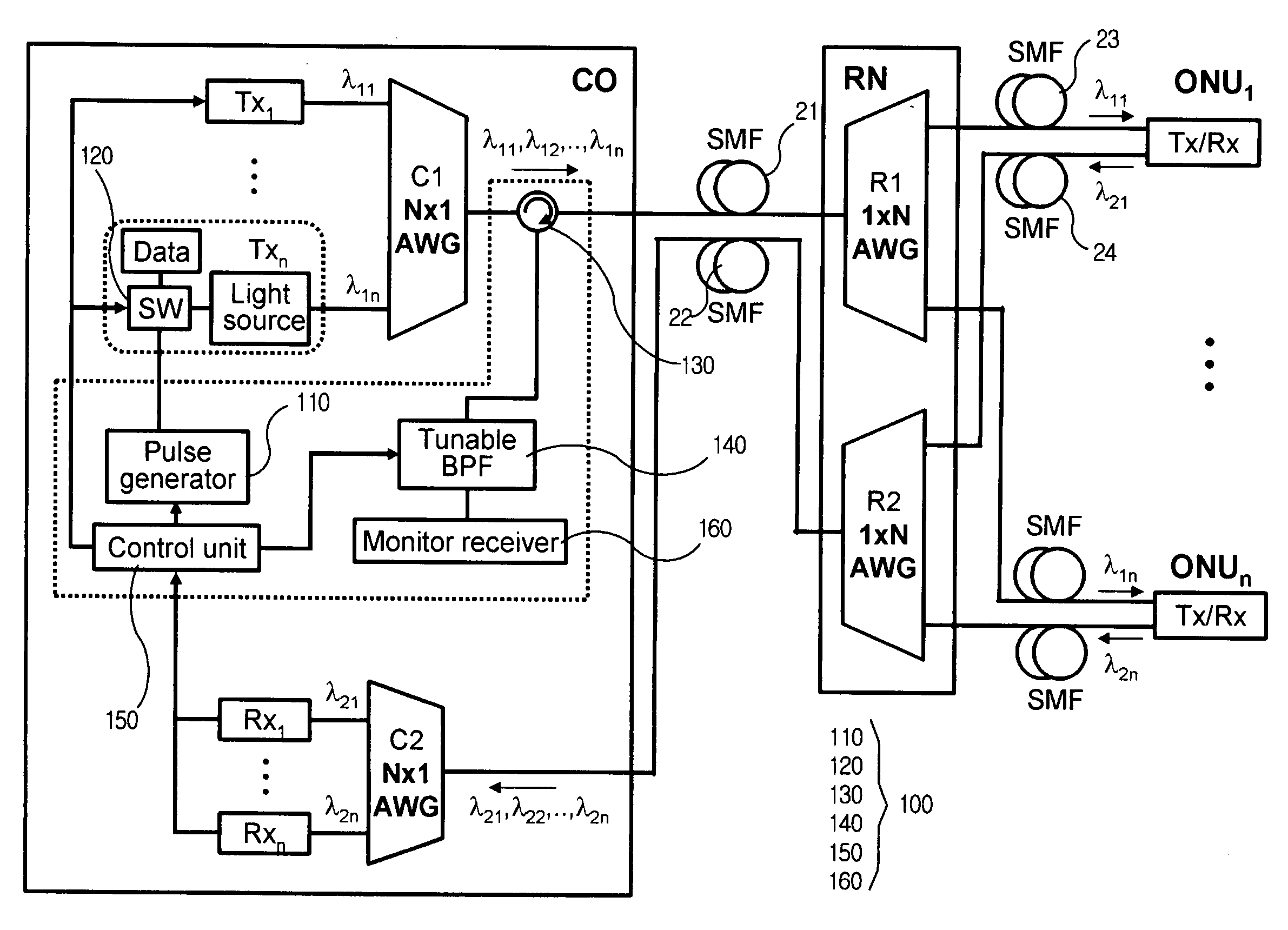
[0050]FIG. 2 is a block diagram of a bi-directional wavelength division multiplexed passive optical network in which a fault localization apparatus for an optical line according to a first embodiment of the present invention is installed.

[0051] Referring to FIG. 2, a central office CO of a WDM PON includes a multiplexer which is configured by an AWG and is connected to downstream transmitters Tx, hereinafter the multiplexer is referred to as C1 N×1 AWG, and a demultimplexer which is configured by an AWG and connected to upstream receivers Rx, hereinafter the demultiplexer is referred to as C2 N×1 AWG. A remote node RN includes a multiplexer / demultiplexer (hereinafter, referred to as R1 1×N AWG), which is configured by an AWG and performs multiplexing and demultiplexing. The R1 1×N AWG is connected to the C1 N×1 AWG and C2 N×1 AWG in the central office through a first optical line 11 and a WDM coupler as a passive element, and is connected to the optical network units through a plur...

embodiment 2

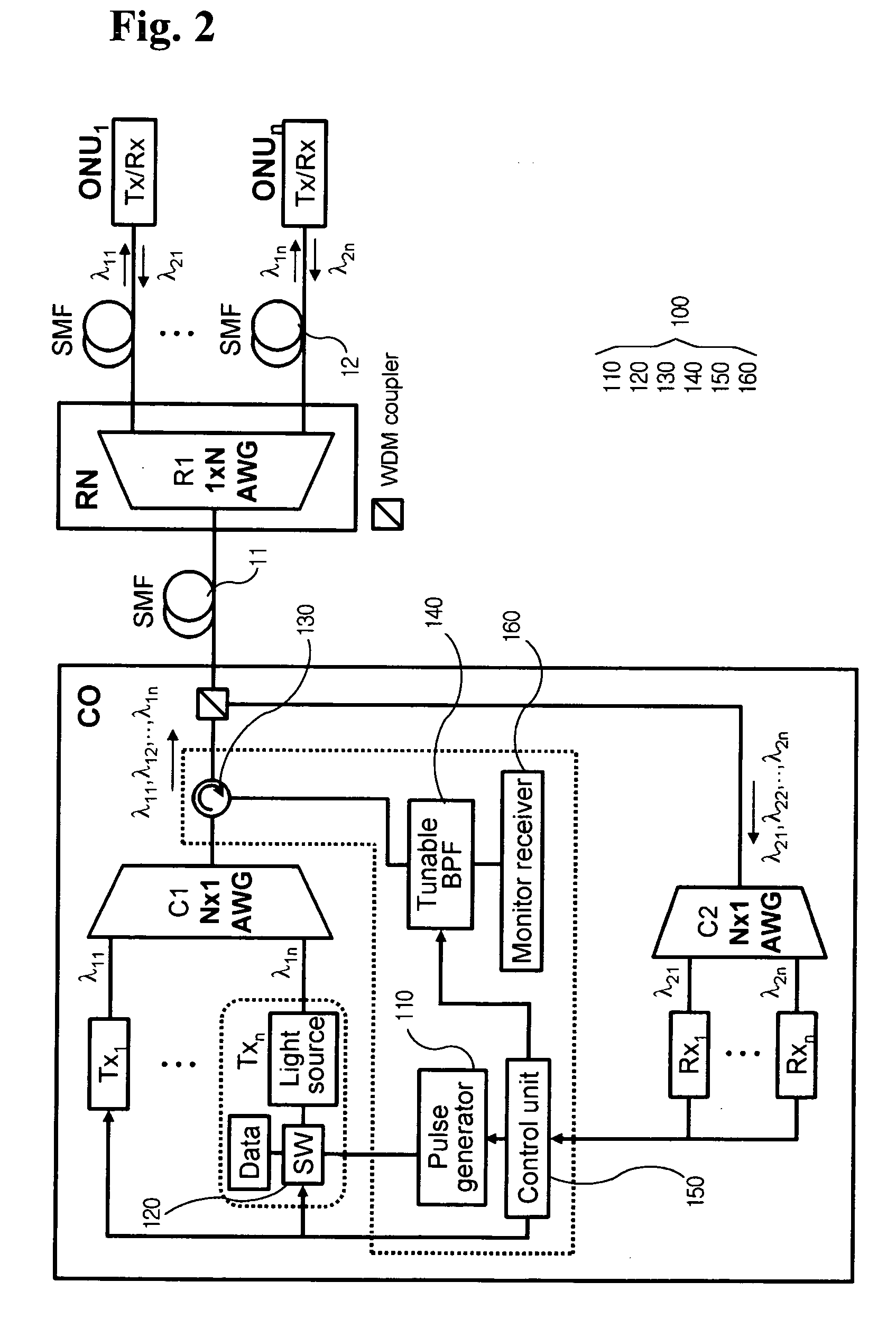
[0066]FIG. 3 is a block diagram of a unidirectional wavelength division multiplexed passive optical network in which a fault localization apparatus for an optical line according to a second embodiment of the present invention is installed.

[0067] The concept of the second embodiment of the present invention is identical to that of the first embodiment, except for constructions of WDM PONs therebetween. Therefore due to such a slight difference in the construction of the WDM PONs, configuration and operation of the fault localization apparatuses are also different. In the description of the second embodiment of the present invention given below, description of elements identical to those of the first embodiment will be omitted.

[0068] Referring to FIG. 3, a central office CO of a WDM PON includes a multiplexer which is configured by an AWG and connected to downstream transmitters, in which the multiplexer is hereinafter referred to as C1 N×1 AWG, and a demultiplexer which is configur...

embodiment 3

[0071]FIG. 4 is a block diagram of a unidirectional wavelength division multiplexed passive optical network in which a fault localization apparatus for an optical line according to a third embodiment of the present invention is installed.

[0072] The third embodiment of the present invention is constructed such that the fault localization apparatus for an optical line 100 according to the present invention is installed in the WDM PON of the second embodiment based on channels. As such, since the apparatus is installed in each channel, the third embodiment does not need such a wavelength tunable band pass filer of the second embodiment, and, instead, has advantages in that, when faults are simultaneously or successively encountered in more than one of third optical lines connecting with a remote node and optical network units, positions of such faults can be detected.


PUM


Abstract

A fault localization apparatus for an optical line in a wavelength division multiplexed passive optical network is disclosed. The apparatus can detect light loss and fault positions as a channel exhibiting an abnormal receiving state of signals received by each of the upstream receivers is checked, and a monitoring optical signal is used, in which the monitoring optical signal is generated as a pulse is inputted to a light source of the downstream transmitter corresponding to the channel showing such an abnormal receiving state. The apparatus according to the present invention can detect fault positions of optical lines between the central office and the remote nodes and between the remote nodes and the optical network units, since the light source of downstream channel in which faults occur is used as a monitoring light source. The apparatus according to the present invention can be cost-effectively implemented.

Description

BACKGROUND OF THE INVENTION [0001] 1. Field of the Invention [0002] The present invention relates to a fault localization apparatus for an optical line, and more particularly to a fault localization apparatus for an optical line in a wavelength division multiplexed passive optical network (WDM PON) in which a downstream light source of a channel having a fault, as a monitoring light source, is used. [0003] 2. Description of the Related Art [0004] Recently, as various data services are rapidly increased through the Internet, a large amount of transmission capacity is needed in a subscriber network. In order to efficiently comply with such requirement, a wavelength division multiplexed passive optical network (WDM PON) has attracted considerable attention. Here, the WDM PON is capable of providing a large number of services as optical signals whose wavelengths are different from each other are provided to each subscriber, and a plurality of optical signals are performed by wavelength ...

Claims


Application Information

Patent Timeline
Patent Type & Authority Applications(United States)
IPC IPC(8): H04J14/00
CPCH04B10/0771H04J14/0226H04J14/025H04J14/0246H04J14/0282A61F11/006A61M2205/587
Inventor CHUNG, YUN CHURSON, EUI SEUNGLIM, KYUNG WOOHAN, KWAN HEE
Owner KOREA ADVANCED INST OF SCI & TECH
Why Eureka
Try Eureka