Laser welding seam with reduced end-crater and process for production thereof

a laser beam welding and end crater technology, applied in the direction of manufacturing tools, mechanical equipment, fastening means, etc., can solve the problems of reducing the problem slightly, but generally not adequately

Active Publication Date: 2006-10-05
DAIMLER AG
View PDF3 Cites 14 Cited by
  • Summary
  • Abstract
  • Description
  • Claims
  • Application Information

AI Technical Summary

Benefits of technology

[0010] The task is solved thereby, that the seam end is provided at a location, which exhibits an excessive material relative to the surrounding surface or thereby, that the seam towards the seam end exhibits a counter-running direction change of its preferred direction, which is designed in such a manner, that as a consequence of the interaction between cooling forward and counter-running seam a backfill of the melt towards the seam end occurs.

Problems solved by technology

These procedures reduce the problem slightly, but generally not adequately.

Method used


Image

  • Laser welding seam with reduced end-crater and process for production thereof
  • Laser welding seam with reduced end-crater and process for production thereof

Examples


Embodiment Construction

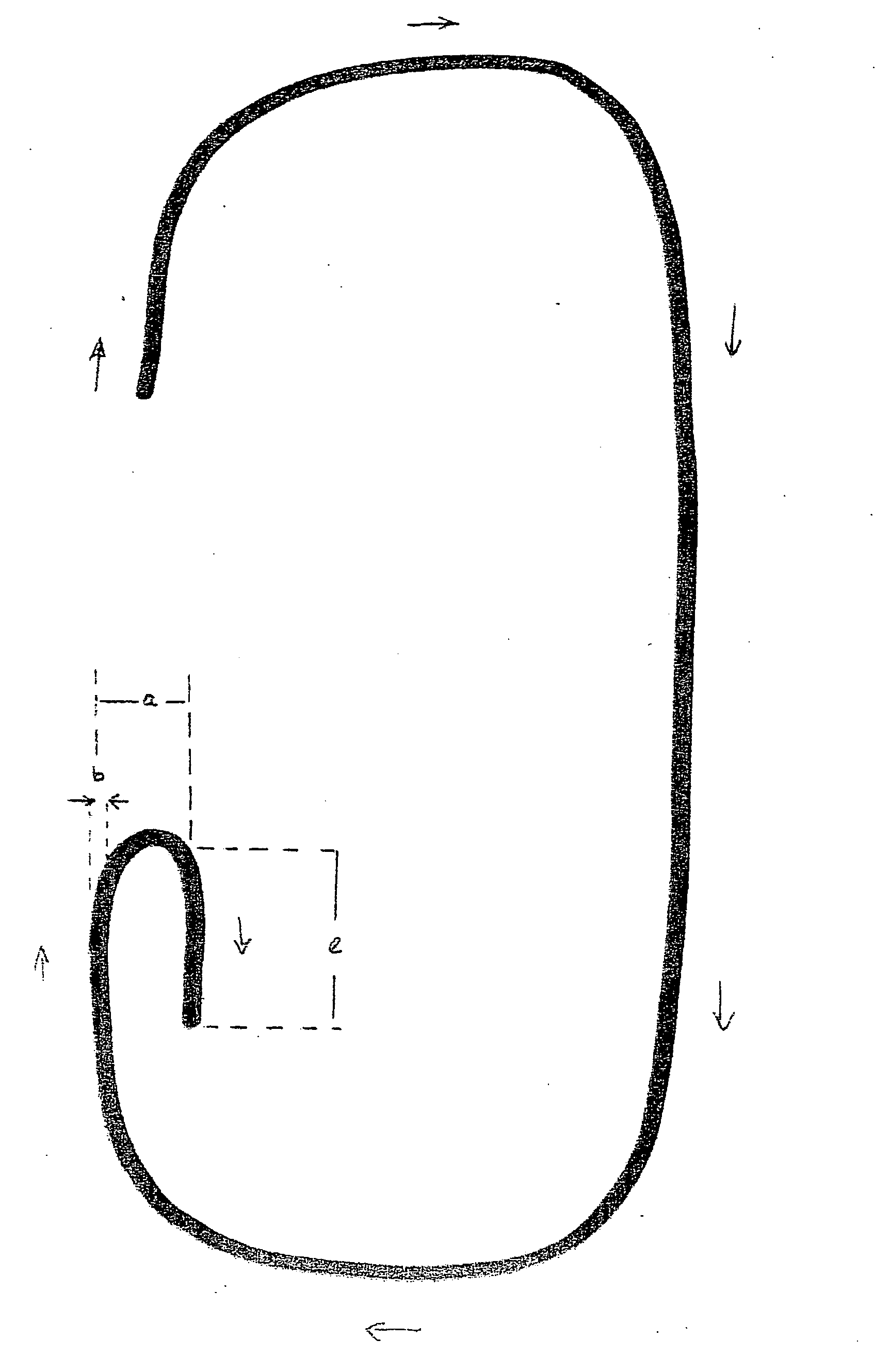
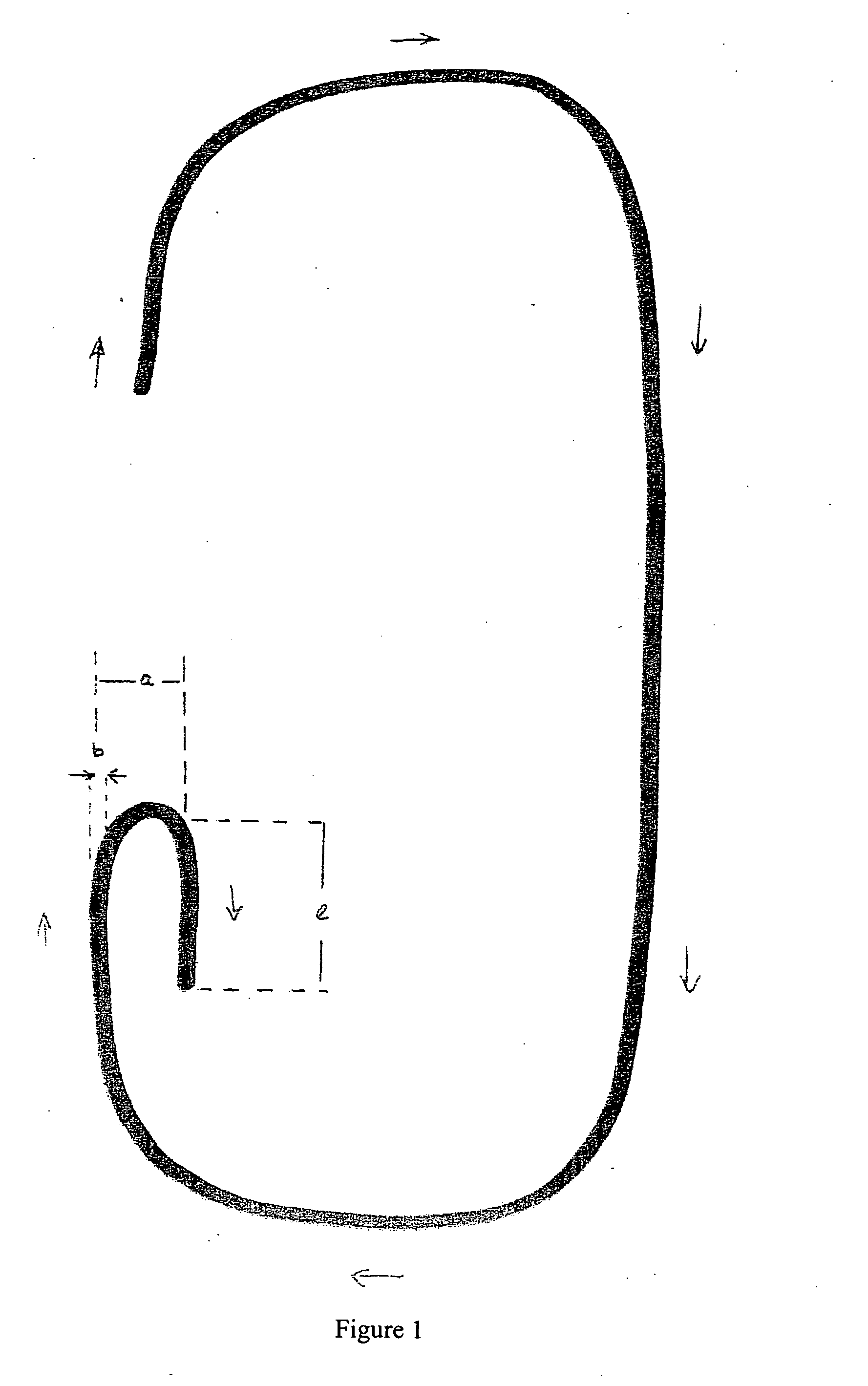
[0012] With regard to the laser weld seam to be provided, the task is inventively solved thereby, that the seam end is positioned at a location, which has an excess of material relative to the surrounding surface.

[0013] The excess material is likewise melted by the welding laser beam and fills in the crater formed at the seam end as a consequence of volumetric shrinkage of the produced melt and thereby substantially reduces this or as the case may be in the ideal case eliminates it completely.

[0014] In one preferred embodiment the material excess is formed as a local topographic change projecting from the surface.

[0015] One such topographic change projecting from the surface can be produced for example according to DE 10 241 593 A1, in which the laser beam describes a decreasing spiral about its processing surface. One such topographic change can be produced independent of the laser weld seam or also during the production thereof.

[0016] A further possibility for producing a topo...


PUM

PropertyMeasurementUnit
diameteraaaaaaaaaa
lengthaaaaaaaaaa
distanceaaaaaaaaaa

Abstract

During laser beam welding a so-called end crater forms at the end of the weld seam. The end crater is formed by the volume shrinkage of the solidifying melt after the laser beam reaches the seam end and is switched off or repositioned. The end crater acts as a geometric notch or groove and deteriorates the mechanical properties of the weld seam, so that holes or tears in the area of the end crater can occur. The task of the present invention as comprised therein, of providing a laser weld seam with reduced end crater and a process for production thereof. The task is solved thereby, that the seam end is provided at a location, which exhibits a excessive material relative to the surrounding surface or thereby, that the seam towards the seam end exhibits a counter-running direction change of its preferred direction, which is designed in such a manner, that as a consequence of the interaction between cooling forward and counter-running seam a backfill of the melt towards the seam end occurs.

Description

CROSS REFERENCE TO RELATED APPLICATION [0001] This application claims the benefit of German Application No. DE 10 2005 004 787.4-34 filed Feb. 1, 2005. BACKGROUND OF THE INVENTION [0002] 1. Field of Invention [0003] The invention concerns a process for laser beam welding with reduced formation of end craters. [0004] During laser beam welding a so-called end crater forms at the end of the weld seam. The end crater is formed by the volume shrinkage of the solidifying melt after the laser beam reaches the seam end and is switched off or repositioned. The end crater acts as a geometric notch or groove and degrades the mechanical properties, and in particular the operational stability, of the weld seam, so that holes or tears in the area of the end crater can occur. [0005] 2. Related Art of the Invention [0006] For reducing the formation of end craters, it is taught in DE 196 30 521 A1 to reduce the laser output at the seam end (so-called “power ramp”) or to increase the weld speed (so-c...

Claims


Application Information

Patent Timeline
Patent Type & Authority Applications(United States)
IPC IPC(8): B23K26/28
CPCB23K26/28Y10T403/477B23K26/422B23K26/702
Inventor BECKER, WOLFGANGBUHLER, JENSFROSCHMEIER, TILMANGOTH, KLAUSKNOLLER, MARKUSREINIGER, CLAUS-DIETERZAUNER, DANIEL
Owner DAIMLER AG
Why Eureka
Try Eureka