Foundation system for prefabricated houses

a foundation system and prefabricated house technology, applied in the direction of fencing, building types, constructions, etc., can solve the problems of high cost, undesirable use of materials, and inability to provide weather-tight structures,

Inactive Publication Date: 2005-02-10
DAVIS S MICHAEL
View PDF34 Cites 7 Cited by
  • Summary
  • Abstract
  • Description
  • Claims
  • Application Information

AI Technical Summary

Benefits of technology

[0007] It is the primary objective of the present invention to provide a precast foundation system specially designed for prefabricated housing which not only serves to secure the home to the earth but also to enclose their lower structural elements in a weather tight and attractive manner.
[0008] It is an additional objective of the present invention to provide such a precast foundation system that does not require that the builder construct concrete footings around the entire perimeter of the prefabricated house which has the effect of reducing building costs through the elimination of excess time and materials in the construction process.
[0009] It is a further objective of the present invention to provide such a precast foundation system that is composed of precast concrete panels and posts that can be assembled into their final configuration on site in an efficient and timely manner that will further reduce construction costs by standardizing the materials and methods used in the building of such structures.

Problems solved by technology

The use of these foundation systems created two separate problems.
The first of these is that they are relatively labor and material intensive resulting in higher costs that to some degree offset the cost saving advantages that are inherent in the factory built methods of constructing housing or other buildings.
Secondly, these types of foundation systems require an additional mechanism to close off the open space between the bottom surface of the structure's rim joist and the surface of the ground.
The use of these materials is undesirable because they form a barrier that is insecure and that requires a great deal of maintenance to keep it in a good state of repair.
Additionally, the use of such construction materials does not provide a weather tight structure that is often necessary in such structures, especially when they are placed in northern areas where there is a need to provide an insulated space between the structure and the surface of the ground.
Finally, the use of these materials results in a finished appearance that clearly indicates that it is a prefabricated structure instead of site-built which is an undesirable result to the eventual owner.
The most obvious problems with this solution is that the use of wood for this purpose is that it results in a foundation system that lacks in structural integrity and which is susceptible to durability problems associated with weathering and material rot.
This adds a degree of difficulty to the operation as it requires that all of these additional structural components be placed in a manner so that they are all exactly level in relation to themselves and the remaining components of the foundation.
The problem with this solution is that the placement of the blocks requires the builder dig a trench and prepare that exposed surface in a manner that will adequately support the blocks and the weight of the structure that they carry.
This method of construction can result is a susceptibility to settling due to inconsistent ground conditions and types.
Additionally, it does not provide a mechanism by which the foundation can compensate for frost heaving conditions that are common in colder climates.
Finally, the provided anchoring system for the footing blocks is not secure enough when considering the loads that they must carry during the course of the structure's life.

Method used


Image

  • Foundation system for prefabricated houses
  • Foundation system for prefabricated houses
  • Foundation system for prefabricated houses

Examples


Embodiment Construction

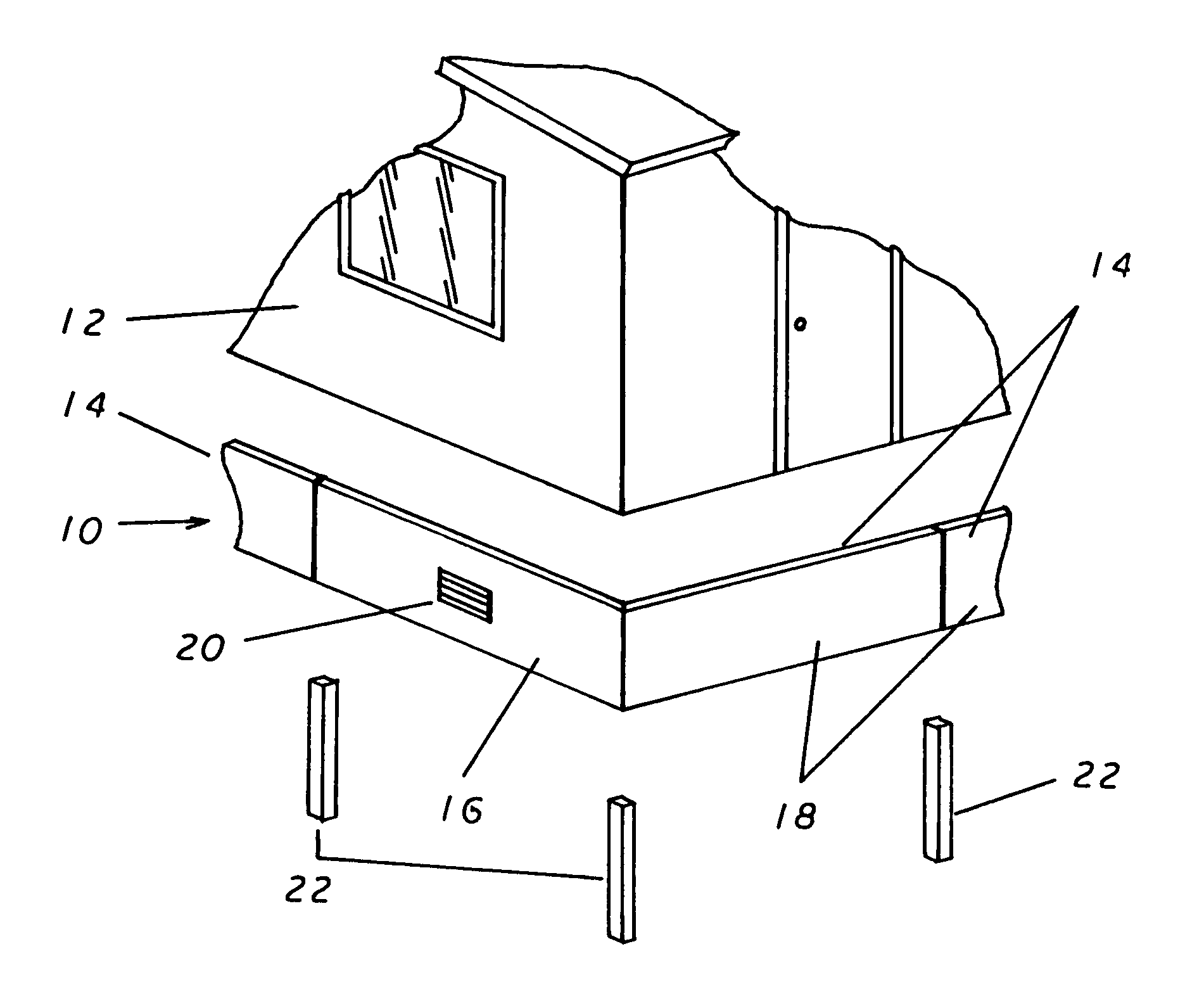
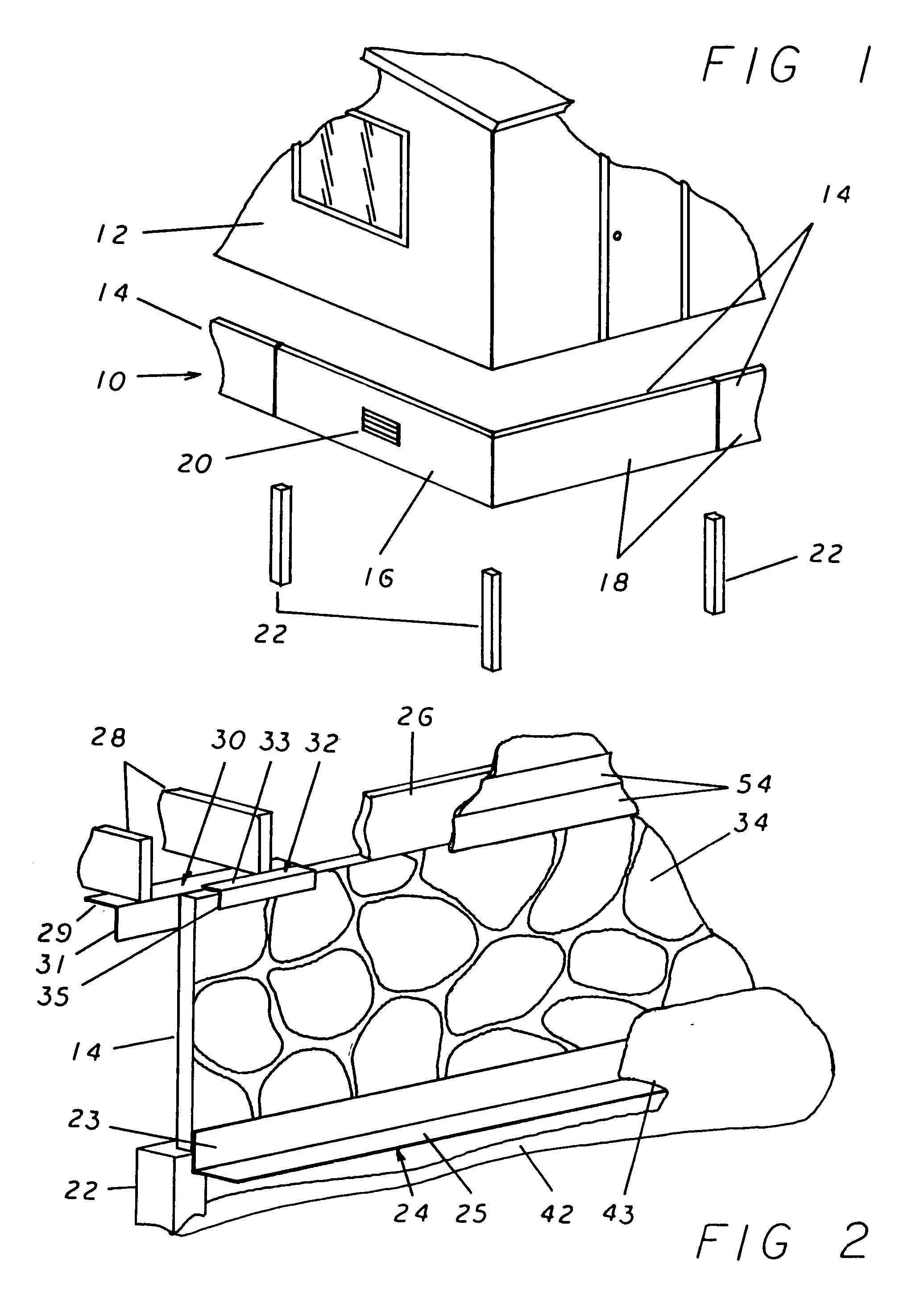
[0023] Referring now to the drawings, and more specifically to FIG. 1 which illustrates the general configuration of the precast foundation 10 and its position relative to the prefabricated structure 12 (in the present instance illustrated as a prefabricated single family home). As illustrated, the precast panels 14 are lined up end to end to form a wall-like structure that forms an enclosing skirt that surrounds the lower perimeter of the prefabricated structure 12. Additionally, the precast panels 14 are either end wall panels 16 or side wall panels 18. The end and side wall panels, 16 and 18, differ only in the fact that the end wall panels 16 can be equipped with vents 20 which provide a mechanism by which the air space beneath the prefabricated structure 12 can interact with the air on the outside. This ensures that the air contained within the space defined by the outside edge of the precast panels 14 will be maintained at the proper temperature and moisture content to avoid t...


PUM


Abstract

A prefabricated foundation is provided using a plurality of concrete panels that are cast at a factory location to a predetermined uniform form and size. These panels are of a generally rectangular shape and are positioned end to end forming a wall-like structure around the entire perimeter of a prefabricated structure. The lower surface of the panels are then supported by a plurality of precast posts that correspond in position and number to the joints between the plurality of panels. The joint between two abutting precast panels is sealed to provide a weather tight fit between the exterior and interior of the panels. The upper edge of the precast panels are locked in position keeping them from moving in either an inward or outward manner thereby providing a stable platform upon which a prefabricated structure can be placed.

Description

BACKGROUND OF THE INVENTION [0001] The present invention relates to an improvement in the foundation system used on prefabricated structures, such as mobile homes or factory manufactured buildings. More specifically, a foundation system made of a plurality of precast panels that rest on precast posts and not only support the panels but also close in the space between the lower surface of the structure in a manner that is both weather tight and aesthetically pleasing. [0002] In the past, prefabricated structures were positioned at their building sites by the use of a poured concrete slab or conventional concrete footings. The use of these foundation systems created two separate problems. The first of these is that they are relatively labor and material intensive resulting in higher costs that to some degree offset the cost saving advantages that are inherent in the factory built methods of constructing housing or other buildings. [0003] Secondly, these types of foundation systems req...

Claims


Application Information

Patent Timeline
Patent Type & Authority Applications(United States)
IPC IPC(8): E02D27/01E04B1/343
CPCE02D27/01Y10S52/03Y10S52/11E04B1/34352
Inventor DAVIS, S. MICHAEL
Owner DAVIS S MICHAEL
Why Eureka
Try Eureka