Fillet machining without adaptive probing and parts finished thereby

a technology of adaptive probing and machining, applied in the direction of forging/pressing/hammering apparatus, program control, instruments, etc., can solve the problems of increasing the chance of machining chatter and requiring extra time, and affecting productivity

Inactive Publication Date: 2005-12-15
GENERAL ELECTRIC CO
View PDF15 Cites 9 Cited by
  • Summary
  • Abstract
  • Description
  • Claims
  • Application Information

AI Technical Summary

Benefits of technology

[0005] There is therefore provided, in some aspects of the present invention, a method for finishing a part having excess material. The method includes generating one or more surfaces on a model of the part to be machined, creating a machining tool path drive geometry, using the machine tool path drive geometry and one or more surfaces on the model to be machined to generate machining tool paths on the surfaces; and running tool paths on the part in a fixture.
[0006] In other aspects, the present invention provides a method for finishing a part having excess material. The method includes generating one or more surfaces on a model of the part to be machined, creating a machining tool path drive geometry, using the machine tool path drive geometry and the one or more surfaces on the model to be machined to create a computer numerical control path for a machining tool on the surfaces, and running tool paths on the part in a fixture.
[0007] In still other aspects, the present invention provides a forged part having airfoil and platform surfaces. The forged part is finished by a method that includes generating one or more surfaces on a model of the part, creating a machining tool path drive geometry, using the machine tool path drive geometry and the one or more surfaces on the model to create a computer numerical control path for a machining tool on the surfaces, and running tool paths on the part in a fixture.

Problems solved by technology

For high volume, short cycle time parts, the extra time required has an adverse effect on productivity.
However, a drawback of this technique is that the end mill can be fully engaged (i.e., the entire radius of the ball is cutting), which usually increases the chance of machining chatter.

Method used


Image

  • Fillet machining without adaptive probing and parts finished thereby
  • Fillet machining without adaptive probing and parts finished thereby
  • Fillet machining without adaptive probing and parts finished thereby

Examples


Embodiment Construction

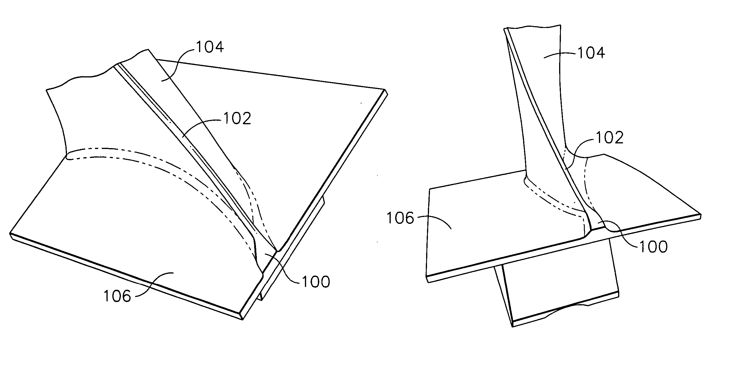
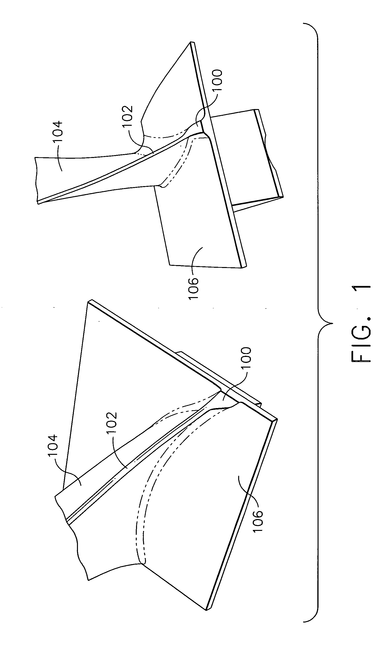
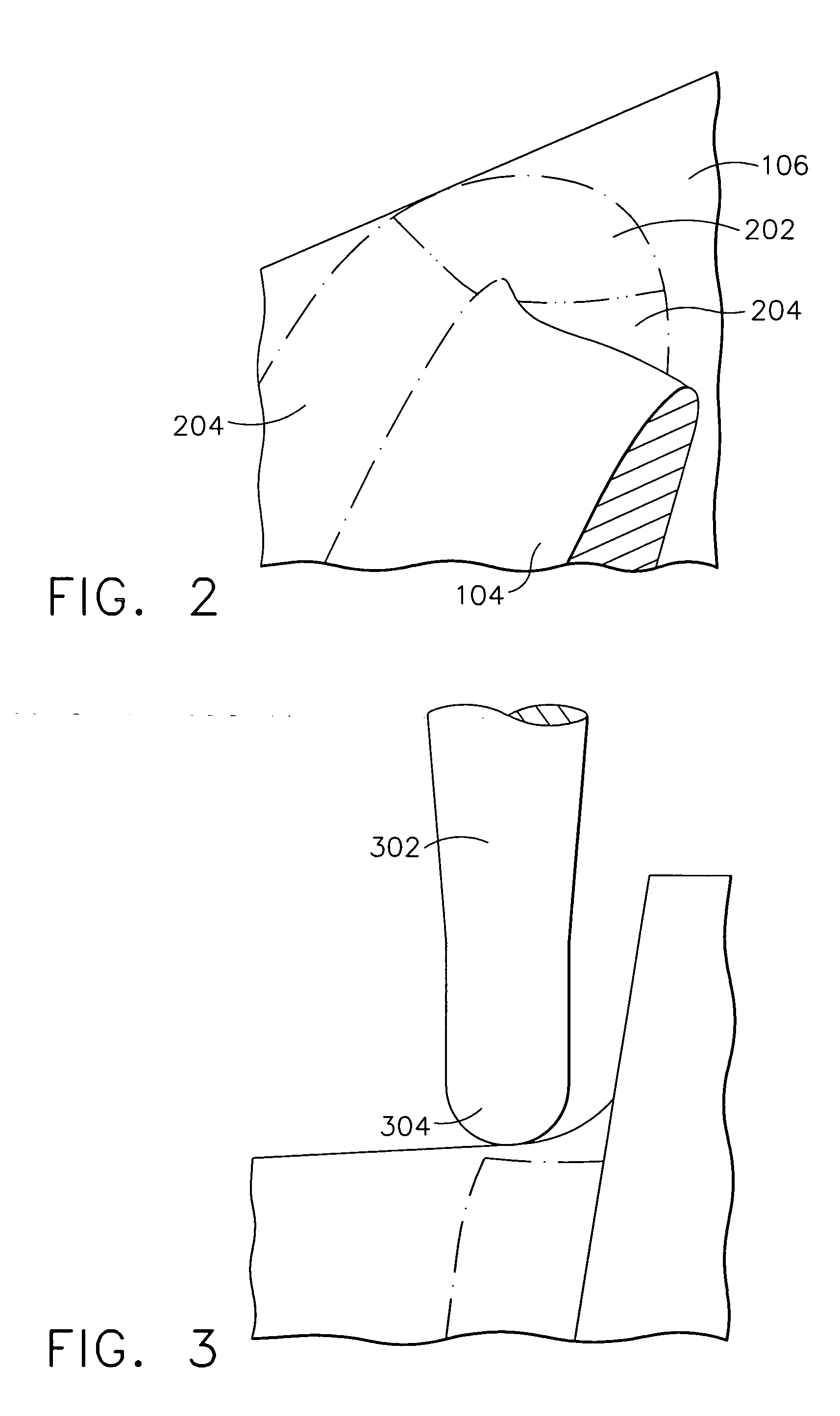
[0014] As a technical effect of the present invention, flexibility in the shape of a machined surface is provided. Other technical effects include facilitating a more continuous mating with, for example, an air foil and platform. In various configurations, another technical effect of the present invention is that an improved surface finish is achieved.

[0015] In some configurations of the present invention, a single point milling technique is provided that uses a smaller ball end mill than is used in root fillet milling. The drive geometry is a surface instead of a curve, and the final shape of the machined surface is controlled by the shape and location of the drive surface rather than the radius of the end mill. These configurations of the present invention provide flexibility in the shape of the machined surface, which in turn facilitates a more continuous mating with the air foil and platform. In general, a true arc is not required at the LE and TE platform fillet. The end mill ...


PUM

PropertyMeasurementUnit
radiusaaaaaaaaaa
radiusaaaaaaaaaa
chordwise lengthaaaaaaaaaa

Abstract

A method for finishing a part having excess material includes generating one or more surfaces on a model of the part to be machined, creating a machining tool path drive geometry, using the machine tool path drive geometry and one or more surfaces on the model to be machined to generate machining tool paths on the surfaces; and running tool paths on the part in a fixture.

Description

BACKGROUND OF THE INVENTION [0001] This invention relates generally to machining of surfaces and to part having machined surfaces, and more particularly, to methods and computer-aided machining of surfaces without the requirement of adaptive probing and to parts produced thereby. [0002] Forging processes used to create some surfaces, for example, airfoil and platform surfaces, can leave excess material at intersections of edges. For example the forging process used to create airfoil and platform surfaces leaves extra material at an intersection between the airfoil lead edge (LE, or thick edge), trail edge (TE, or thin edge) and the platform. In at least one known production operation, a manual process is used to remove this excess material. In this process, referred to as “benching” or “bench blend,” a highly skilled operator grinds away material using a rotating abrasive wheel. The operator must be dedicated to the task and cannot complete any other tasks while conducting the bench...

Claims


Application Information

Patent Timeline
Patent Type & Authority Applications(United States)
IPC IPC(8): B23C3/18B63H1/14B63H1/20F01D5/14
CPCB23C3/18B63H1/14F01D5/141G05B2219/35097G05B2219/35128F05D2240/80Y10T29/49336Y10T409/301736Y10T29/49995Y10T29/49325
Inventor OUELLETTE, RANDALL MAURICECLOSE, JEFFREY ROBERTMADGE, JAMES HENRY
Owner GENERAL ELECTRIC CO
Why Eureka
Try Eureka