Lithographic printing plate support and presensitized plate

Inactive Publication Date: 2006-10-05
FUJIFILM CORP +1
View PDF3 Cites 11 Cited by
  • Summary
  • Abstract
  • Description
  • Claims
  • Application Information

AI Technical Summary

Benefits of technology

[0027] As will be described later, the presensitized plate according to the present invention allows not only the press life but also the resistance to scumming by ink spreading, resistance to scumming by leaving and resistance to scumming by failed deletion, and the water visibility as well, to be excellent, even if an FM screen is used for halftone.
[0028] In other words: An image can be printed with the scumming in non-image areas being prevented even upon FM screen printin

Problems solved by technology

In this regard, ink on one image area and that on an adjacent image area are liable to come into contact with each other (that is to say, ink spreading will readily occur) so as to cause the non-image area between

Method used


Image

  • Lithographic printing plate support and presensitized plate
  • Lithographic printing plate support and presensitized plate
  • Lithographic printing plate support and presensitized plate

Examples


example 1 , examples 6 to 9

Example 1, Examples 6 to 9, and Comparative Examples 6 to 9]

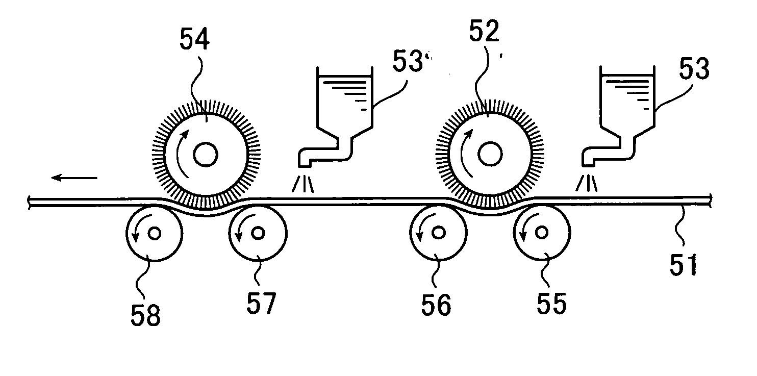
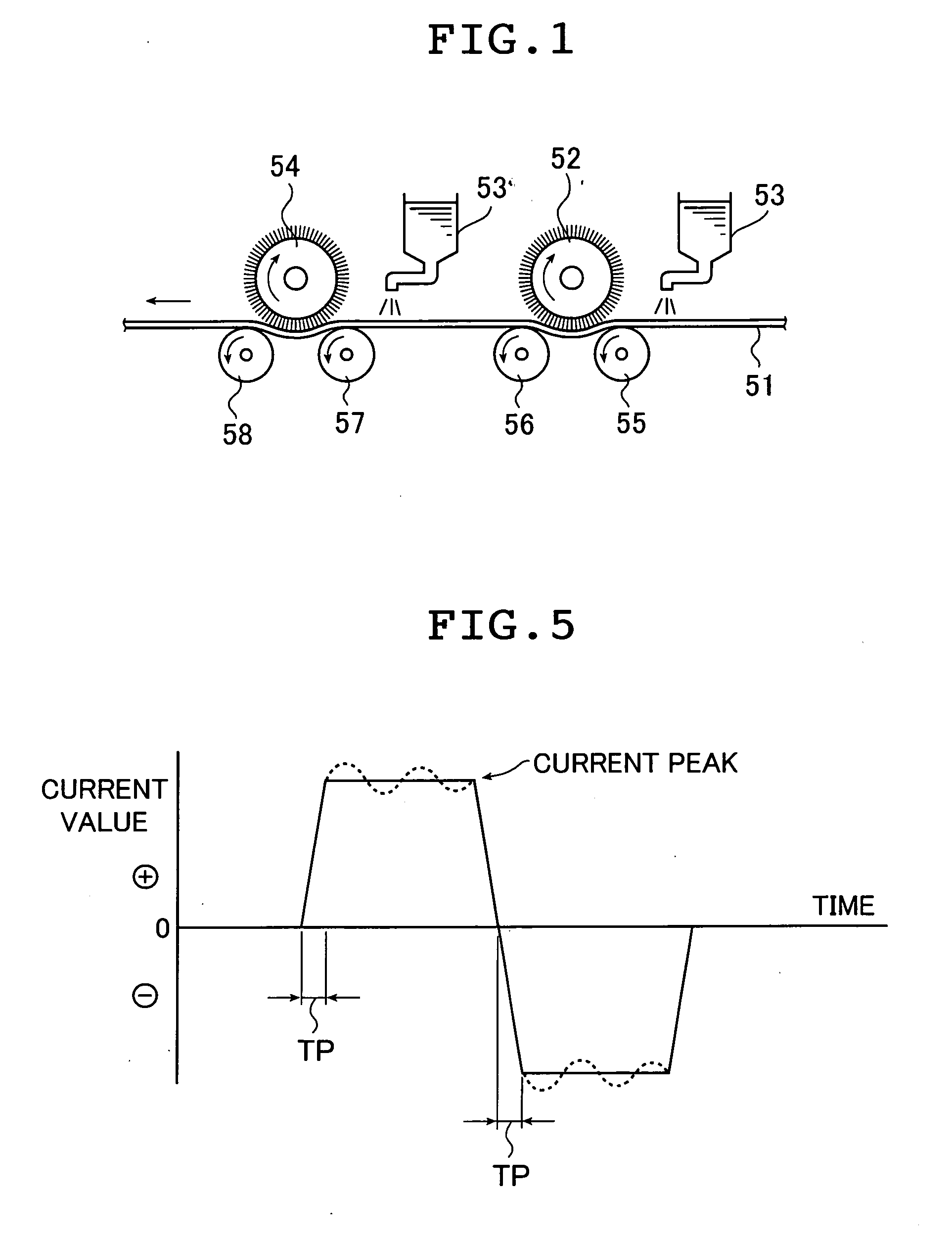
[0401] Lithographic printing plate supports were obtained by subjecting aluminum plates (JIS A1050 material) with a thickness of 0.3 mm to the graining treatments as below. After each treatment or rinsing process, the solution or water remaining on the plates was removed with nip rollers.

[0402] Graining was carried out by performing the following surface treatments (a) to (e). sequentially.

[0403] (a) Alkali Etching Treatment

[0404] Etching treatment was performed for 10 seconds by spraying the aluminum plates as above with an aqueous solution having a caustic soda concentration of 30 g / L, an aluminum ion concentration of 10 g / L and a temperature of 60° C. so as to dissolve the plates in an amount of 0.5 g / m2. Then, the aluminum plates were rinsed with a spray of water.

[0405] (b) Desmutting Treatment

[0406] Desmutting treatment was performed by spraying the aluminum plates with a 12 g / L aqueous solution of nitric acid (co...

example 2

[0423] A presensitized plate was fabricated by following the procedure of Example 1 except that the current density was 12 A / dm2 and the amount of electricity was 300 C / dm2 in treatment (c) as above. The surface roughness Ra of the lithographic printing plate support obtained after the anodizing treatment was 0.34 μm.

example 3

[0424] A presensitized plate was fabricated by following the procedure of Example 1 except that the current density was 24 A / dm2 and the amount of electricity was 600 C / dm2 in treatment (c) . The surface roughness Ra of the lithographic printing plate support obtained after the anodizing treatment was 0.64 μm.


PUM

PropertyMeasurementUnit
Lengthaaaaaaaaaa
Lengthaaaaaaaaaa
Fractionaaaaaaaaaa

Abstract

Disclosed is a lithographic printing plate support obtainable by subjecting an aluminum plate to an electrochemical graining treatment with an aqueous solution containing hydrochloric acid, anodizing treatment and alkali metal silicate treatment at least, wherein: a surface of the support has a grained shape in which large pits with a mean aperture diameter of 2 to 10 μm and small pits with a mean aperture diameter of 0.05 to 0.8 μm overlap with each other, with the mean ratio of depth to aperture diameter of the small pits being 0.2 to 0.6; a surface area difference ΔS50 defined by equation (1):
ΔS50=(Sx50−S050)/S050×100 (%)   (1)
in which Sx50 is the actual area of a 50 μm square region of the surface as determined by three-point approximation from three-dimensional data obtained by measuring the region with an atomic force microscope at 512×512 points and S050 is the geometrically measured area of the same region, is 20 to 40%; the alkali metal silicate treatment is performed using an aqueous solution of pH 11.5 to 13.0 which contains an alkali metal silicate; and an amount of Si atoms deposited to the surface is 3.0 to 15.0 mg/m2. The presensitized plate according to the present invention allows not only the press life but also the resistance to scumming by ink spreading, resistance to scumming by leaving and resistance to scumming by failed deletion, and the water visibility as well, to be excellent, even if an FM screen is used for halftone.

Description

[0001] The entire contents of the documents cited in this specification are herein incorporated by reference. BACKGROUND OF THE INVENTION [0002] The present invention relates to a lithographic printing plate support which is obtained by subjecting an aluminum plate to electrochemical graining treatment, anodizing treatment and alkali metal silicate treatment at least, and a presensitized plate which is fabricated by using such a lithographic printing plate support. [0003] A presensitized plate for lithographic printing is generally fabricated by subjecting the surface of an aluminum plate to graining treatment such as mechanical graining treatment and electrochemical graining treatment and further to anodizing treatment so as to form an anodized layer, and forming a photosensitive layer (hereafter also referred to as “image recording layer”) on the anodized layer by applying thereto a photosensitive solution and causing the solution to dry. On such a presensitized plate, imagewise e...

Claims


Application Information

Patent Timeline
IPC IPC(8): G03F7/00
CPCB41C2201/04B41N1/083C25F3/04B41N3/038B41N3/034
Inventor HOTTA, HISASHI
Owner FUJIFILM CORP
Why Eureka
Try Eureka