Method and apparatus of optimizing the IO collar of a peripheral image

Inactive Publication Date: 2006-10-05
GOOGLE LLC
View PDF5 Cites 1 Cited by
  • Summary
  • Abstract
  • Description
  • Claims
  • Application Information

AI Technical Summary

Benefits of technology

[0006] In a first aspect of the invention, a method of reducing the die size of an IC chip includes the steps of determining a minimum number of IO cells required by the IC chip, and arranging the minimum number of IO cells in rows of

Problems solved by technology

Since IO cells can only occupy the IO sites, the unused IO sites are wasted space.
IO cells tend to be very large compared to the other logic and, depending on the number of unused IO sites, this wasted space can be a noticeable proportion of the die.
However, it should be noted that typically the chip only utilizes a fraction of the available IO cells.
But, simply removing the inactive IO cells does not reduce the width or height of the combination of chip and IO cells since there are other IO cells along each side of the chip which are required and thus extend the dimension of the chip along that edge.
Accordingly, traditional methods of IO cell layout do not consider the design requirements of the IC chip to optimize space, and thus, traditional IO cell layout methods waste space by requiring unnecessarily large IC chip and IO collar designs.

Method used


Image

  • Method and apparatus of optimizing the IO collar of a peripheral image
  • Method and apparatus of optimizing the IO collar of a peripheral image
  • Method and apparatus of optimizing the IO collar of a peripheral image

Examples


first embodiment

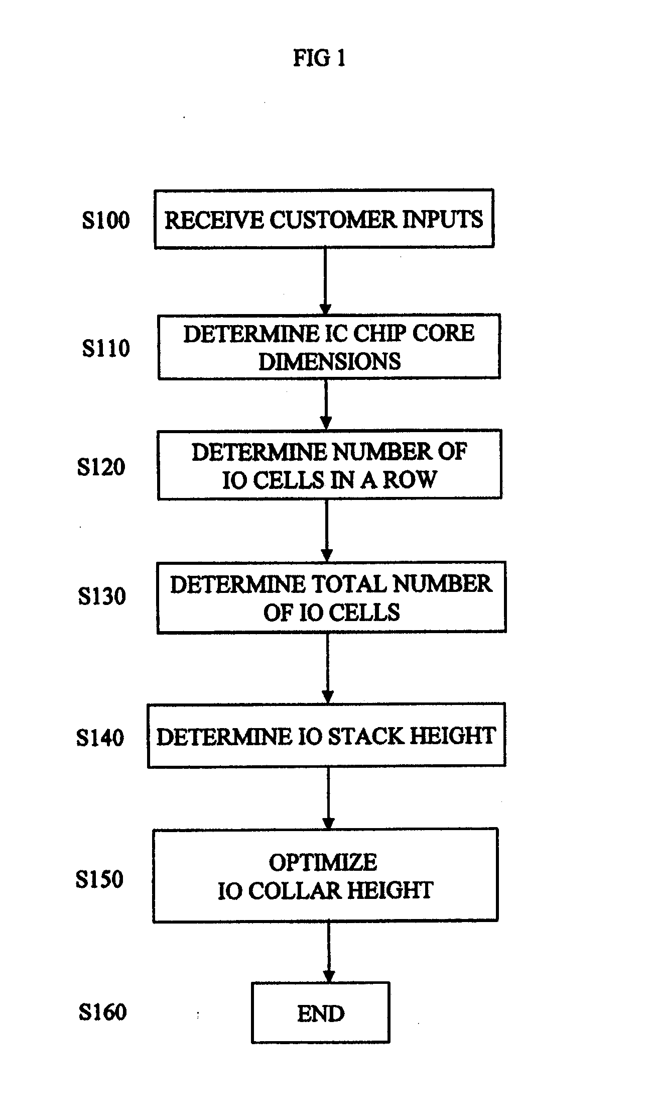
[0035] Referring to FIG. 1, steps of a method for optimizing an IO collar is shown where the first step includes receiving the customer inputs S100. Next, an IC chip core dimensions are determined, which may include determining the aspect ratio of the IC core cell area (S110). As used herein, “IC core cell” is synonymous with “IC core.” Typically, determining the aspect ratio includes finding the smallest core size and aspect ratio to meet total number of core cells (CELLS)>=CELLS_required. For example, the aspect ratio may not equal one in order to optimize for the constraints described in “Required customer inputs” above.

[0036] Next, the number of IO cells per row is determined (S120). Specifically, the number of rotated IOs in a single row that can fit around the IC chip is determined. After the number of rotated IO cells in a single row around the chip is found, the total number of needed IO cells is found (S130). This is done by taking the total SIO count plus the number of unu...

third embodiment

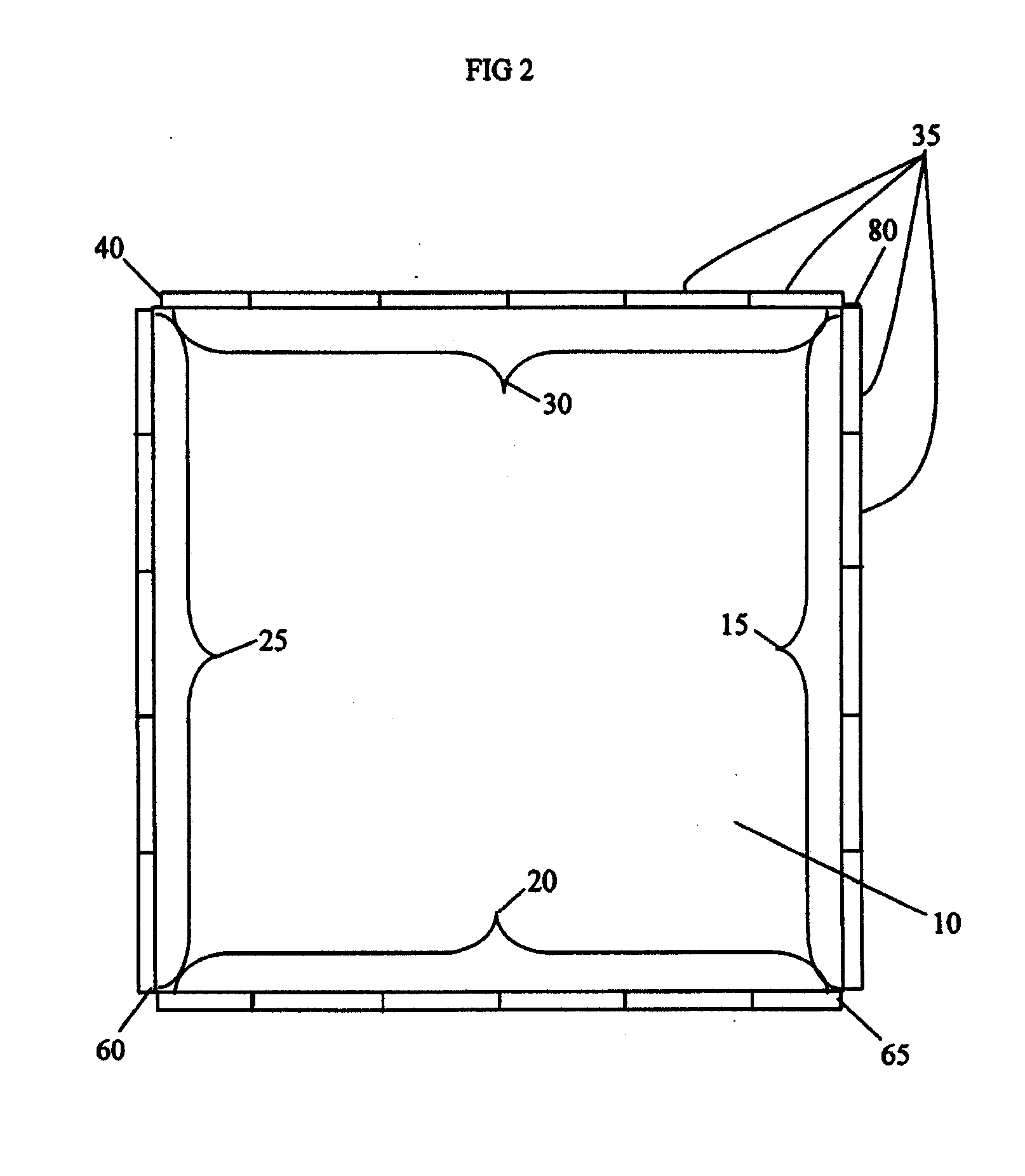
[0057] Referring to FIG. 8, another example of an IO collar produced by the third embodiment is shown. In FIG. 8, an IC chip 10 has both rotated 35 and non-rotated 110 IO cells around it. It should be noted that each particular edge of the IC chip 10 could have only rotated IO cells 35 or non-rotated IO cells 110. Accordingly, the edge 15 of the IC chip 10 has a single row 120 of non-rotated IO cells 110. Similarly, the edge 25 has a single row 115 of non-rotated IO cells 110. The edge 20 of the IC chip 10 has three rows 65, 70, and 75 of rotated IO cells 35. The edge 30 has four rows 40, 45, 50, and 55 of rotated IO cells 35. As such, the edge 20 and the edge 30 both contain rotated IO cells 35, however, each edge has a different number of rows of IO cells 35. Accordingly, the number of rotated IO cells 35 may be adjusted on each edge to optimize the size of the IO cell collar.

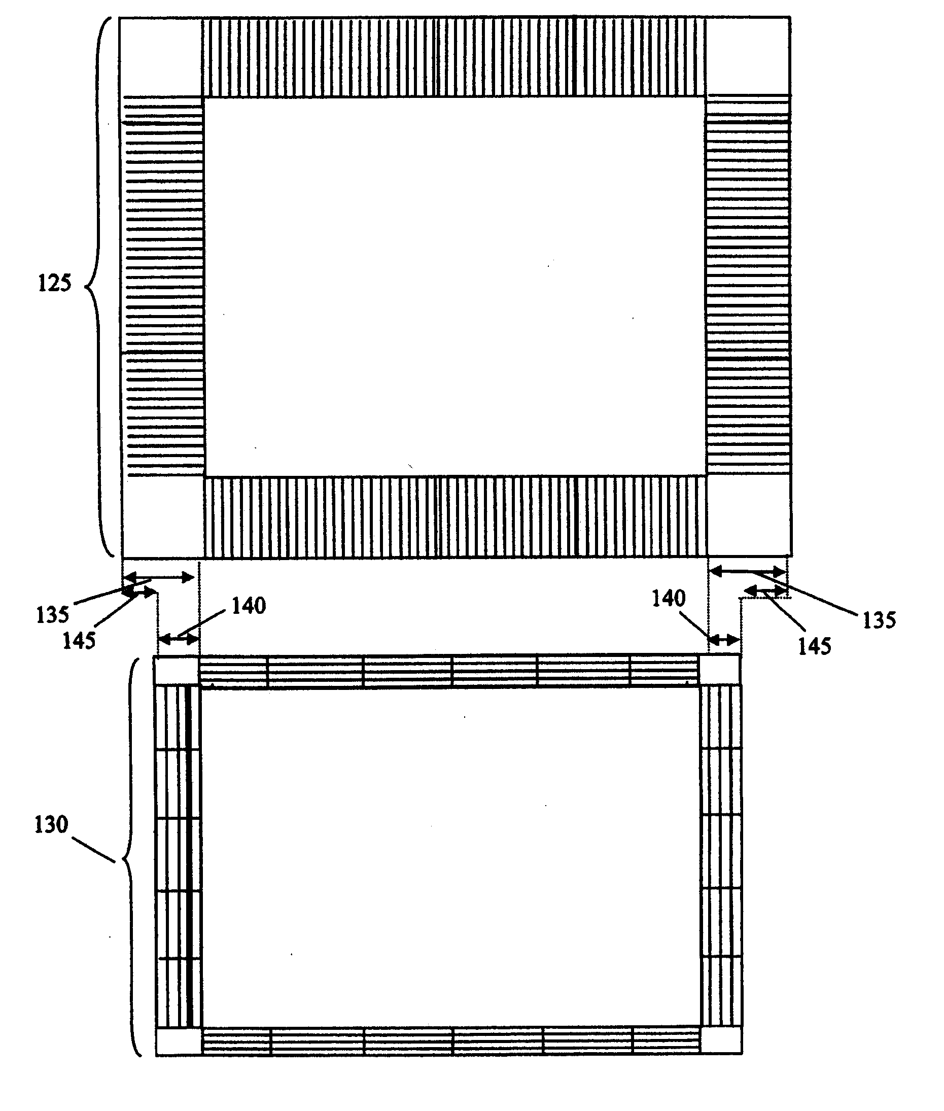
[0058] Referring to FIG. 9, the overall size of an IC chip and associated traditional IO collar 125 is sho...


PUM


Abstract

An apparatus and method for optimizing the size of an IO collar and reducing the die size of an IC chip is provided. The method and apparatus includes arranging rotated IO cells around the edges of the IC chip to reduce the number of unused IO cells in the IO collar. All the IO cells may be rotated, or a combination of rotated and non-rotated IO cells may form the IO collar. For each edge of the IC chip having rotated IO cells, each edge may have the same number of stacks of IO cells or a different number of stacks of IO cells.

Description

FIELD OF THE INVENTION [0001] The invention relates to circuit layout and design methods, and more particularly to the layout of IO cells on an integrated circuit chip. BACKGROUND DESCRIPTION [0002] Many ASIC wirebond chips are not IO-limited, meaning the image / package can support more IOs than the design requires. In some designs the internal logic of the design of the IC chip dictates the size and thus more IO cells than are needed are formed in the IO collar surrounding the IC chip. Since IO cells can only occupy the IO sites, the unused IO sites are wasted space. IO cells tend to be very large compared to the other logic and, depending on the number of unused IO sites, this wasted space can be a noticeable proportion of the die. Since the cost to manufacture a die is directly proportional to the area of the die, it is desirable to make the die as small as possible. [0003] An IO cell tends to be rectangular in shape, and typically in a peripheral IO chip the long side of the IO c...

Claims


Application Information

Patent Timeline
IPC IPC(8): G06F17/50
CPCG06F17/5072G06F30/392
Inventor CHUNG-MALONEY, WAI LINGITO, HARUOSTOUT, DOUGLAS W.
Owner GOOGLE LLC
Why Eureka
Try Eureka