Contemporary DRAM-based memory devices have become increasingly dense as the desire for more memory storage increases.
Therefore, the overall reduction in size of DRAM memories has not been reduced as much as is desired.
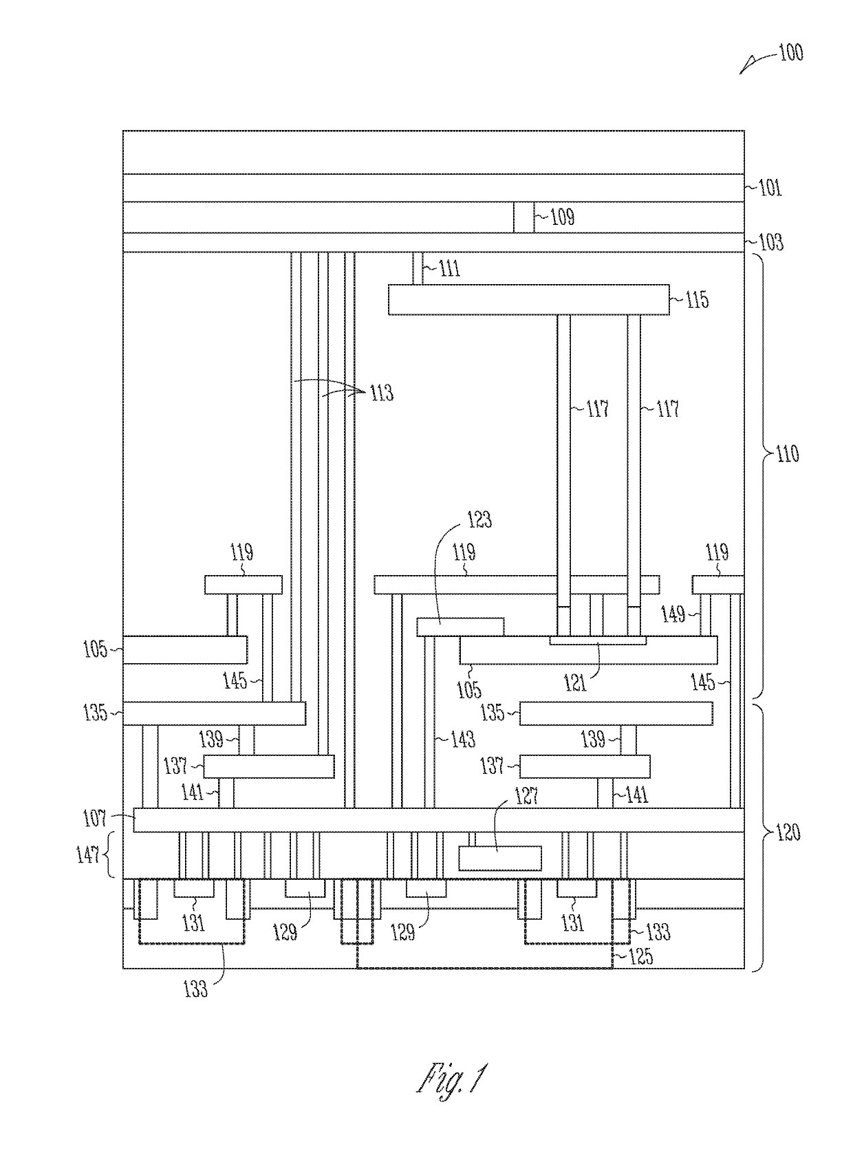
While highly-generalized forms of the peripheral circuits under a
DRAM memory array concept comes from NAND and other cross-point memory devices where it has been implemented, there are distinct differences between DRAM and other memory types, described in detail below, that have previously proved to be too challenging to implement for DRAM devices.
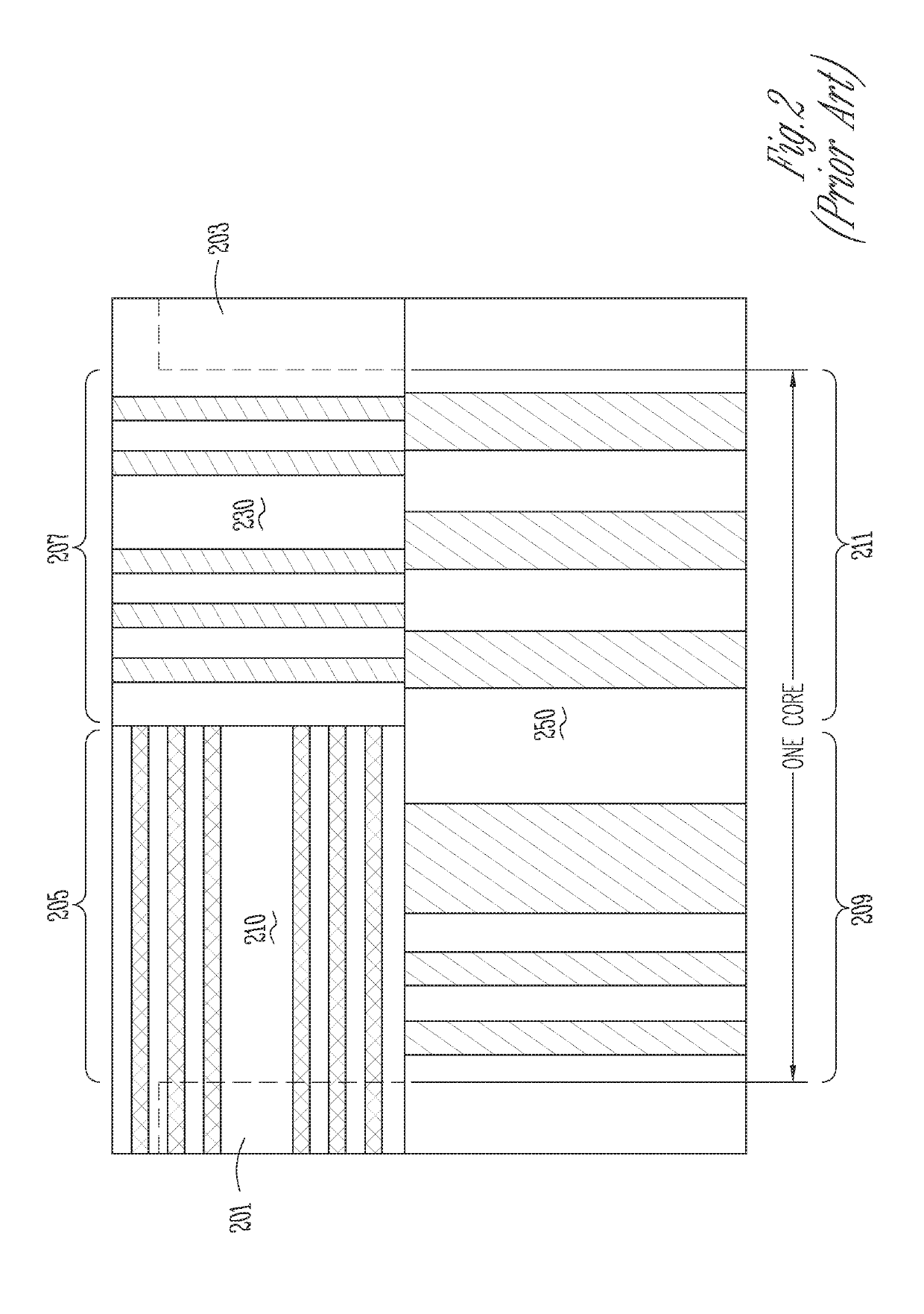
Although the WL and DL
pitch sizes have been reduced significantly in recent years, other required DRAM peripheral components have failed to be reduced in size proportionately.
Consequently, the overall reduction in die size has not approached expected levels.
As noted above, while the
memory cell has shrunk, the
pitch cells have not been able to keep up proportionally, making them a larger percentage of die size.
The additional thermal effects can cause detrimental effects to certain types of materials.
Although, as noted above, related concepts have been considered in, for example, NAND and other cross-point memory devices, there are significant process,
memory operation, and speed requirement differences between these memory types and
DRAM memory.
For example, there are limitations on current ratios for transistors in the support circuitry (e.g.,
ion and ioff current ratios), thereby requiring a minimum
metal line size to prevent
electromigration and related issues.
However, with various technologies employed today, the
capacitor size is only about 50% to 60% of the die size.
Therefore, although the
capacitor size has been reduced significantly (e.g., through the use of trench capacitors, stacked capacitors, etc.), the overall die size cannot be reduced further without significant reductions in the associated
footprint of the peripheral circuitry.
In addition, due to additional functionality incorporated in DRAM memory designs recently (e.g., error correction circuitry,
equalization transistors for enhanced pre-charge, decoder complexity due to increased array capacities, changes in
cell design (e.g., 1T1C to 3T1C, etc.), the size of the peripheral circuitry has actually increased.
Despite these advantages, forming peripheral circuits under the memory array has never been attempted for at least the reasons noted above.
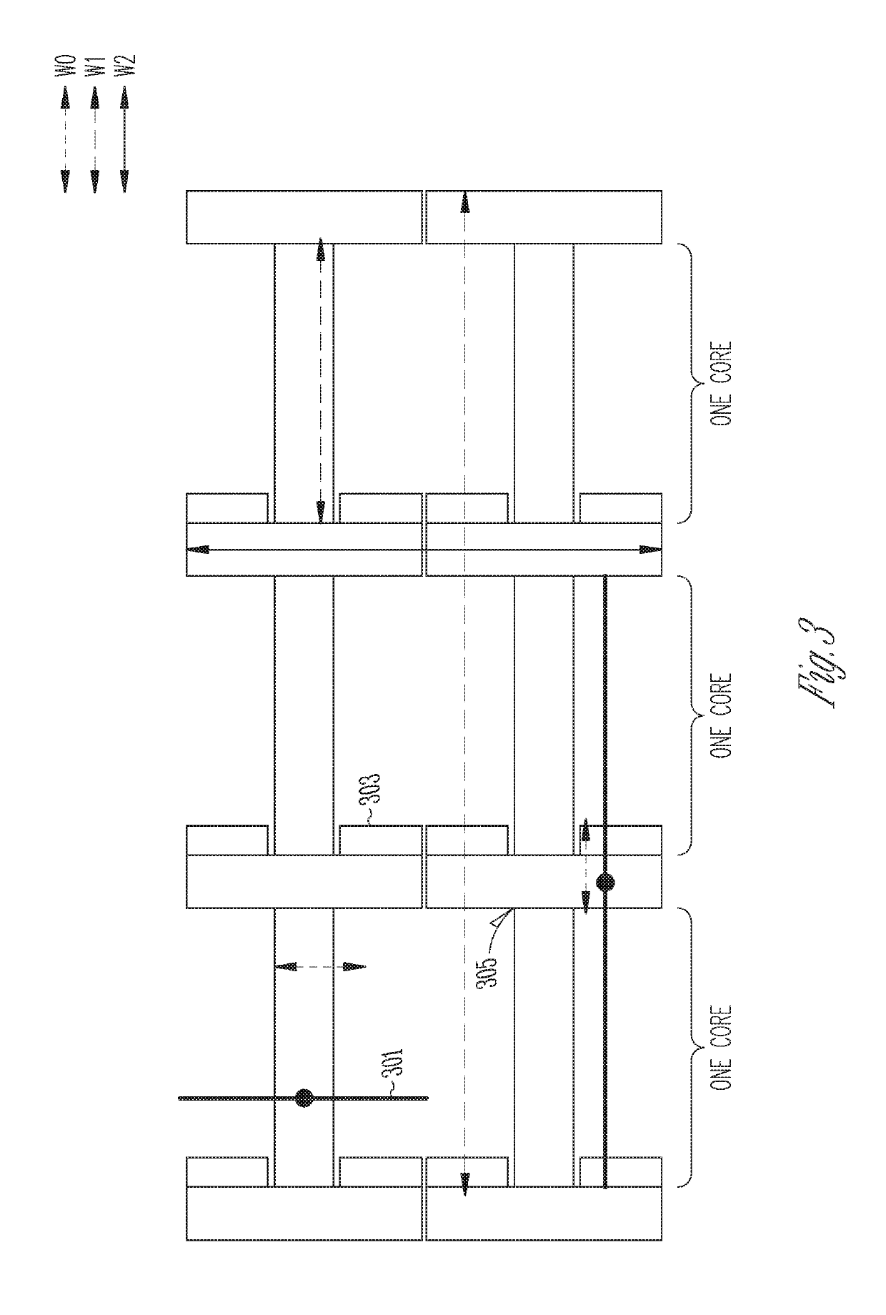
However, at this small pitch, the thickness is correspondingly small, thereby making the
tungsten lines highly resistive.
Formation of the WL and DL lengths will benefit from precision formation (e.g., within 10 nm to 15 nm) at the stagger, which may be challenging with current fabrication technology.
In this embodiment, all the pitch cells can be placed under the array, with a small inefficiency due to any extra termination and dummy cells if needed.

