Tank seal for guided wave radar level measurement

Active Publication Date: 2006-10-12
ROSEMOUNT INC
View PDF23 Cites 84 Cited by
  • Summary
  • Abstract
  • Description
  • Claims
  • Application Information

AI Technical Summary

Problems solved by technology

Since the process materials within the tank tend to be corrosive and are often stored under pressure, there is a process seal positioned between the sensor and the potentially aggressi

Method used


Image

  • Tank seal for guided wave radar level measurement
  • Tank seal for guided wave radar level measurement
  • Tank seal for guided wave radar level measurement

Examples


Embodiment Construction

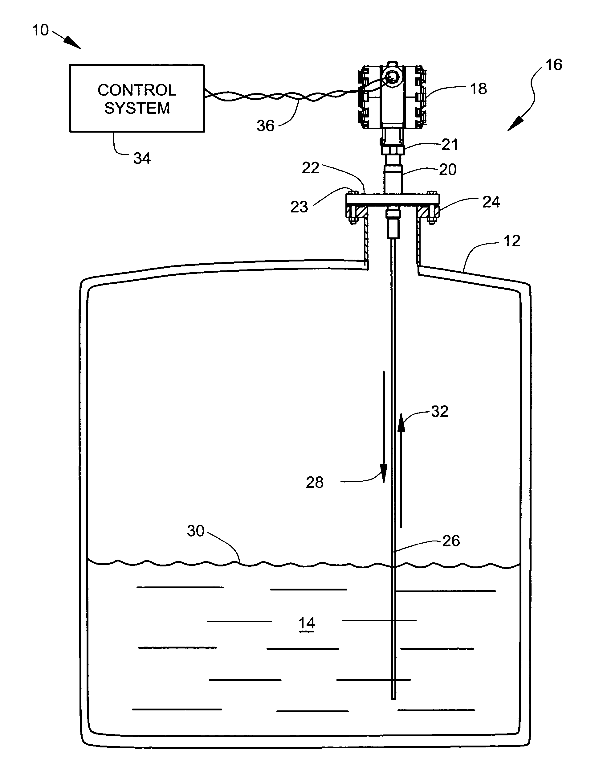
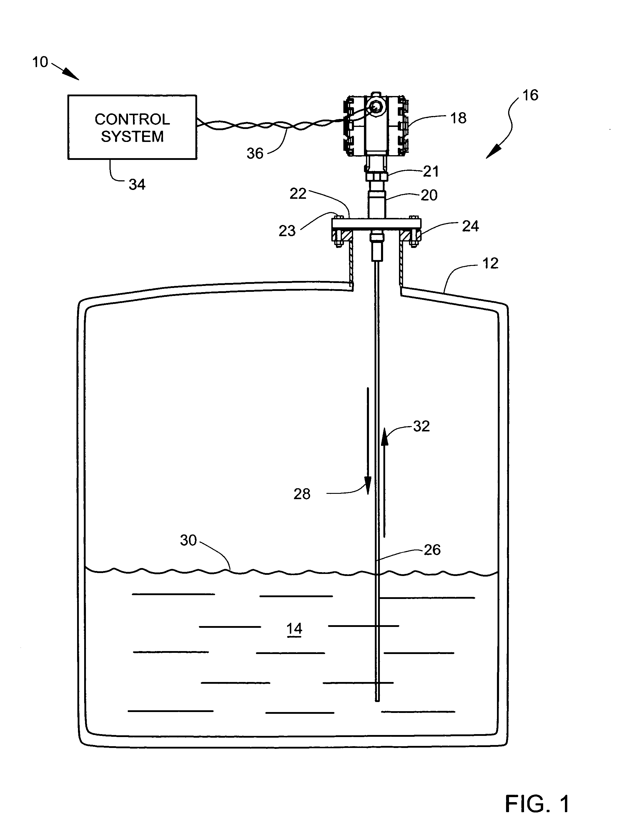
[0017]FIG. 1 is an illustration of a tank level monitoring system 10. The system 10 includes a process tank 12, shown in cross-section, which is filled with a process material 14. A microwave level gauge assembly 16 is mounted to the tank 12. Generally, the process tank 12 is filled with the process material 14, the height or level 30 of which is to be measured by the microwave level gauge assembly 16.

[0018] The microwave level gauge assembly 16 includes a transmitter housing 18 attached to an adapter body 20 by a threaded coupler nut 21. The threaded coupler nut 21 functions as part of a separation joint so that the transmitter housing 18 can be conveniently removed for servicing. The threaded coupler nut 21 also functions as part of a union joint so that the transmitter housing 18 can be assembled to the adapter body 20 in any rotational position for convenience in connecting an electrical wiring conduit to the transmitter housing 18. The adapter body 20 is coupled to the tank 12...


PUM


Abstract

A microwave level gauge for measuring a level of a process material in a tank includes a ceramic seal and a microwave conductor. The ceramic seal is disposed adjacent to an opening in the tank and adapted to isolate circuitry from the process material. The microwave conductor is electrically coupled to the circuitry and extends through the hermetic seal and into the process material in the tank. The ceramic seal and an isolating adapter cooperate to isolate the microwave conductor from the process fluid and from external forces.

Description

BACKGROUND OF THE INVENTION [0001] The present invention relates to a microwave level gauge adapter having a thermal barrier for use with a tank level sensor. [0002] Level gauges are generally used in the process control industry to measure the level of material contained in a tank. As used herein, the term “tank” refers to a container, receptacle, vessel or other device for holding gases, liquids or solids. Radar level gauges are often used to measure process fluids or process solid levels in tanks, where the process materials range from benign materials to severely corrosive or abrasive compounds. [0003] One type of level gauge for measuring a level of material in a tank is called a microwave level gauge. Microwaves are high frequency, short wavelength, electromagnetic waves. Microwaves, because of their short wavelengths, tend to travel in straight lines. This property gives rise to their application in radar, where objects are detected by the reflection of microwaves. [0004] Gen...

Claims


Application Information

Patent Timeline
IPC IPC(8): G01F23/00
CPCG01F23/284
Inventor GRAVEL, JAMES L.FANDREY, MARK C.
Owner ROSEMOUNT INC
Why Eureka
Try Eureka