
Engine bore liner cassette and method

Inactive Publication Date: 2006-10-12
GM GLOBAL TECH OPERATIONS LLC
View PDF10 Cites 2 Cited by
  • Summary
  • Abstract
  • Description
  • Claims
  • Application Information

AI Technical Summary

Benefits of technology

[0006] Consistent and consonant with the present invention, a bore liner cassette wherein an accuracy in positioning of each of the

Problems solved by technology

Many known bore liners are produced from cast iron since wear resistance is high and wear resistance for aluminum alloys used to form engine blocks is low.

Method used


Image

  • Engine bore liner cassette and method
  • Engine bore liner cassette and method
  • Engine bore liner cassette and method

Examples


Embodiment Construction

[0017] The following detailed description and appended drawings describe and illustrate various exemplary embodiments of the invention. The description and drawings serve to enable one skilled in the art to make and use the invention, and are not intended to limit the scope of the invention in any manner. In respect of the methods disclosed, the steps presented are exemplary in nature, and thus, the order of the steps is not necessary or critical.

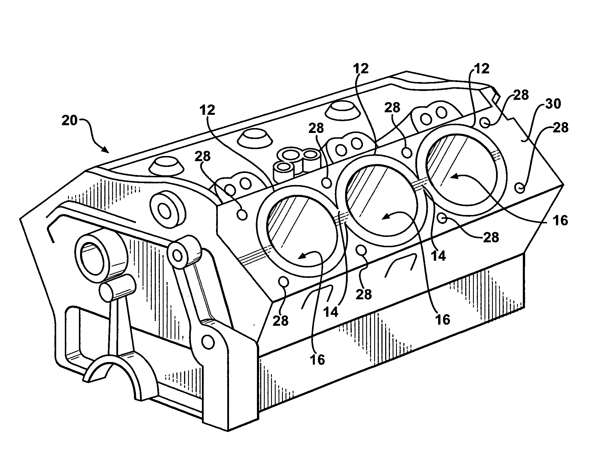
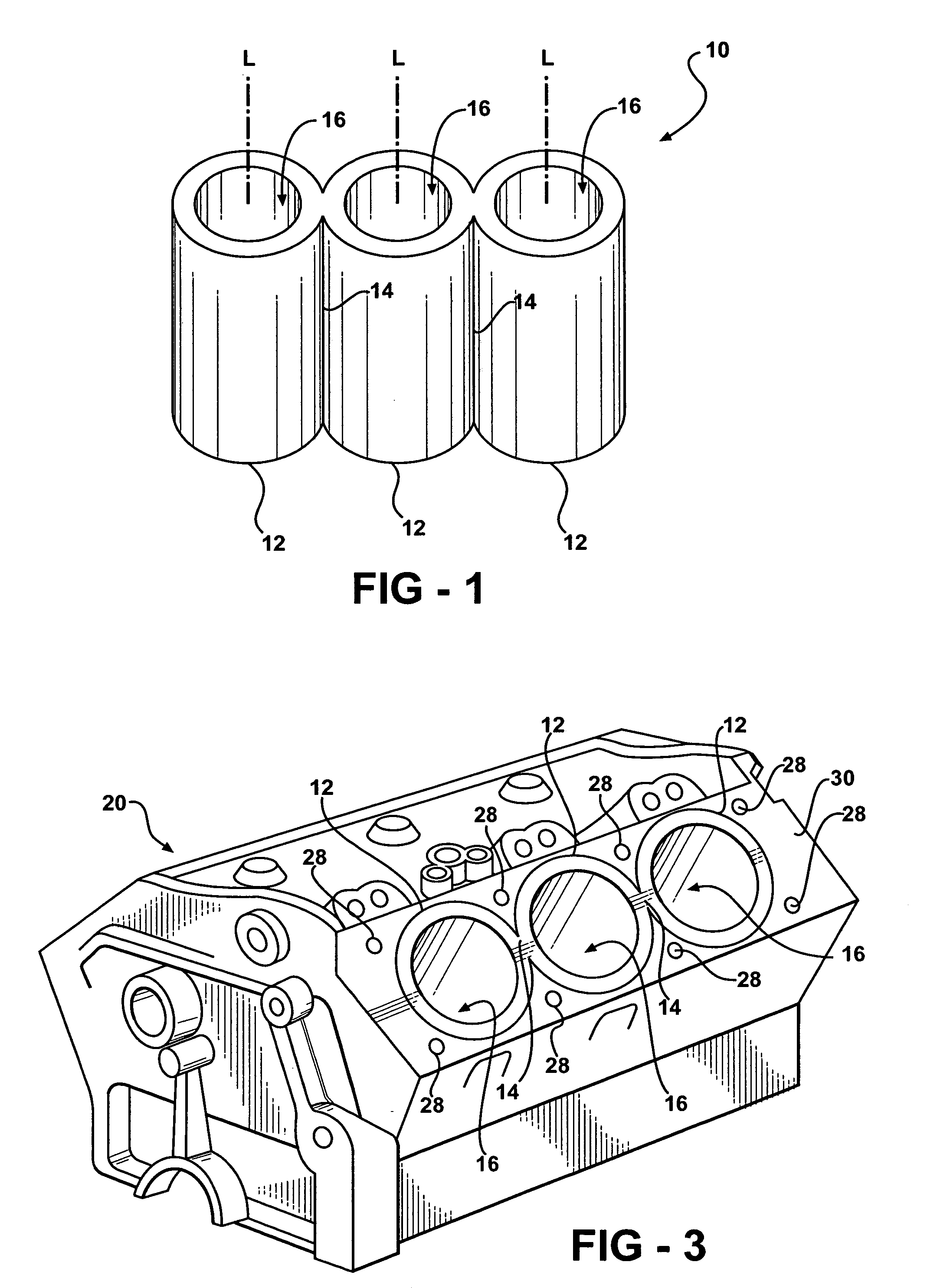
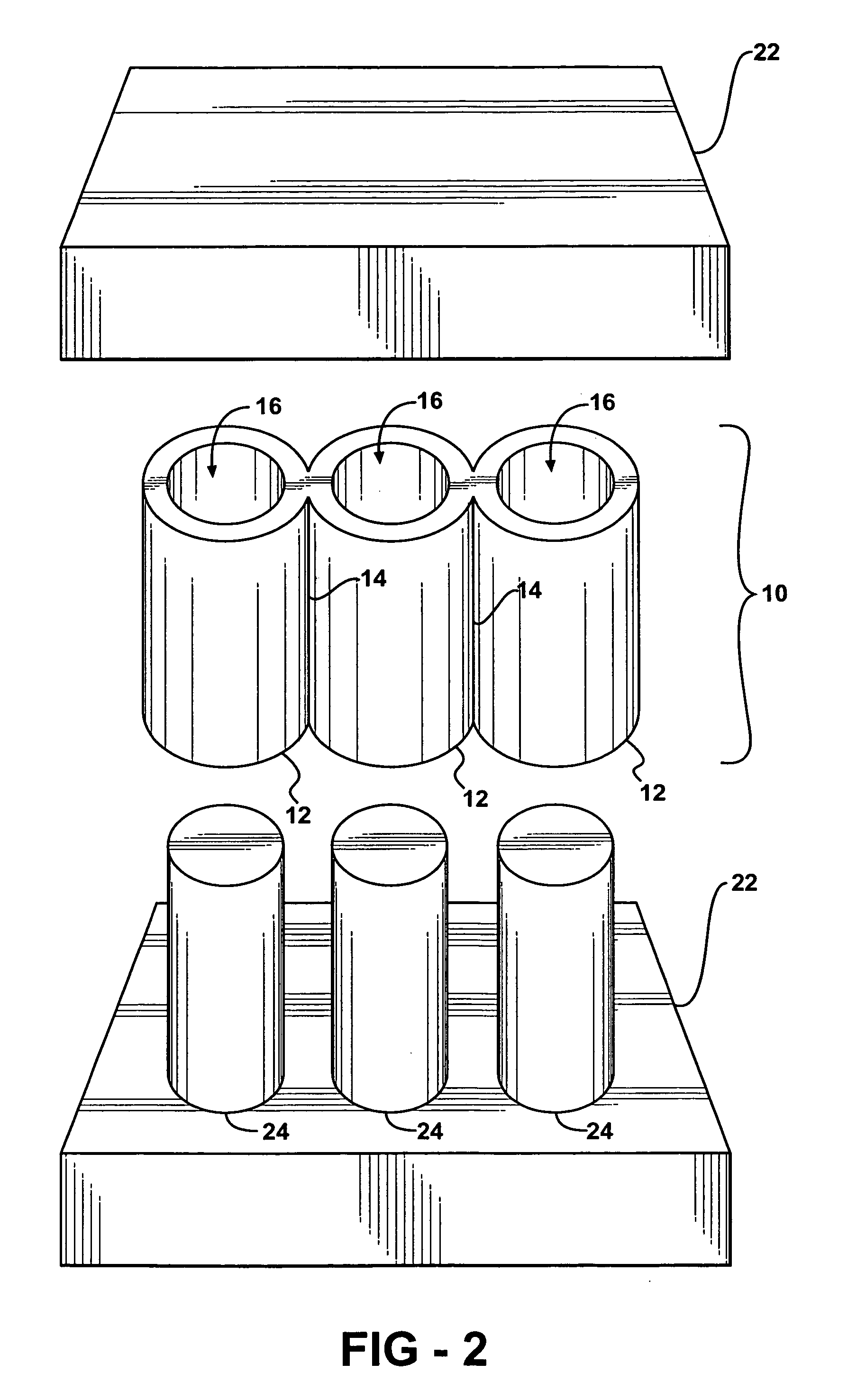
[0018]FIG. 1 illustrates a bore liner cassette 10 according to an embodiment of the invention. As used herein, cassette means a receptacle, a cartridge, a cylinder, and a joined plurality of a receptacle, a cartridge, or a cylinder, for example. In one embodiment, the bore liner cassette 10 is cast using high pressure die casting. Any conventional casting method such as casting with permanent or semi-permanent molds, for example, can be used without departing from the scope and spirit of the invention.

[0019] In the embodiment shown, the b...


PUM

PropertyMeasurementUnit
Fractionaaaaaaaaaa
Fractionaaaaaaaaaa
Fractionaaaaaaaaaa

Abstract

Cast-in-place cylinder bore liners are disclosed for use in casting of engine cylinder blocks, wherein a plurality of the cylinder bore liners are joined to form a cassette, and wherein an accuracy in positioning of each of the bore liners with respect to each other is maximized and a weight thereof is minimized.

Description

FIELD OF THE INVENTION [0001] The invention relates to cylinder bore liners, and more particularly to cast-in-place cylinder bore liners for use in casting of engine cylinder blocks, wherein a plurality of the cylinder bore liners are joined to form a cassette. BACKGROUND OF THE INVENTION [0002] Typically, aluminum die cast engine cylinder blocks are produced with cast-in-place bore liners. Many known bore liners are produced from cast iron since wear resistance is high and wear resistance for aluminum alloys used to form engine blocks is low. [0003] In the manufacture of an aluminum engine with cast-in-place bore liners, for example, a mold assembly method typically involves positioning a base core on a suitable surface and building up or stacking separate mold elements to shape such casting features as sides, ends, valley, water jacket, cam openings, and crankcase. The bore liners are positioned on barrel cores such that the liners become embedded in a casting after molten metal i...

Claims


Application Information

Patent Timeline
IPC IPC(8): F02F1/00
CPCC22C21/02F02F1/18F02F1/045
Inventor WARD, GARY C.POWELL, BOB R. JR.
Owner GM GLOBAL TECH OPERATIONS LLC
Learn More