Sensing an operating parameter of a target concealed from a sensor by an interposed component

a technology of interposed components and operating parameters, which is applied in the direction of instruments, mechanical devices, devices using electric/magnetic means, etc., can solve the problems of only being able to access, adding cost and complexity to mechanical design, hydraulic actuation and electronic control, and indirect access using surrogate speeds in combination with algorithmic corrective calculations, so as to avoid complexity, increase variable cost and manufacturing cost, and mechanical strength of the interposed element according to the present invention

Active Publication Date: 2005-03-17
FORD GLOBAL TECH LLC
View PDF10 Cites 8 Cited by
  • Summary
  • Abstract
  • Description
  • Claims
  • Application Information

AI Technical Summary

Benefits of technology

[0010] Another advantage of the present invention is avoiding need to relocate components in order that a sensor has direct access to a target. Instead, the target component may be covered or otherwise concealed from the sensor, thereby avoiding the complexity and increase variable costs and manufacturing cost that such component relocation causes.
[0011] The interposed, concealing or covering component according to the present invention may be formed of stainless steel that is resistant to martensite formation, which is a crystalline phase transformation that frequently occurs when a component of stainless steel is formed by stamping. The mechanical strength of the interposed element according to the present invention is high and provides the opportunity to minimize the thickness and weight of that element. The possibility of deforming the part is eliminated because no post-stamping heat treatment is required.
[0012] No separate magnetic ring mounted on the target element is required to enhance the magnetic flux transfer through the speed sensor. A conventional splined surface profile on the target element, or another tooth profile, provides sufficient signal excitation. Importantly, there is no need to compromise the optimal power flow through the transmission by relocating components.

Problems solved by technology

The speed of most components in the case can be accessed directly by magnetic sensing devices, but occasionally such access can only be obtained upon relocating the target component adjacent a sensor.
Frequently these relocations compromise the power flow arrangement in the transmission and add cost and complexity to the mechanical design, hydraulic actuation and electronic controls.
Indirect access using surrogate speeds in combination with algorithmic corrective calculations, in place of the true target speed, sacrifices response time and accuracy.

Method used


Image

  • Sensing an operating parameter of a target concealed from a sensor by an interposed component
  • Sensing an operating parameter of a target concealed from a sensor by an interposed component
  • Sensing an operating parameter of a target concealed from a sensor by an interposed component

Examples


Embodiment Construction

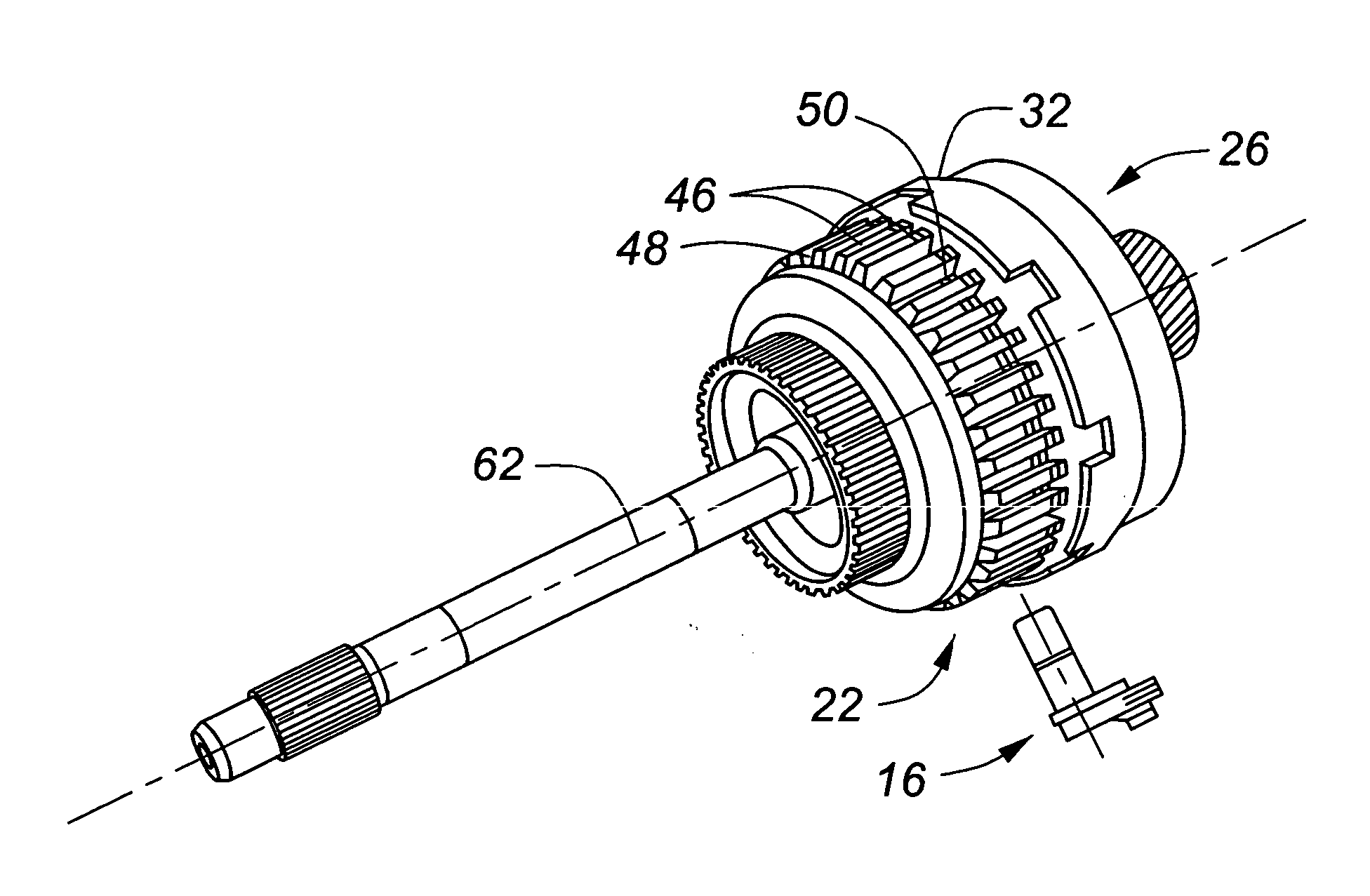
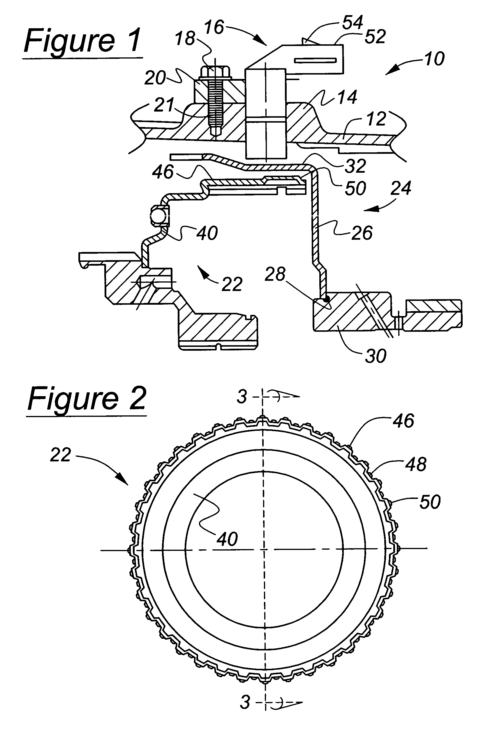
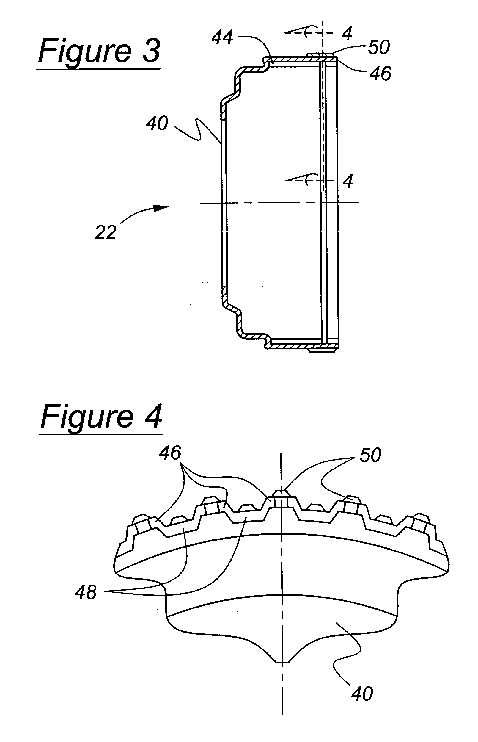
[0024] Turning now to FIG. 1, the components of a transmission 10 are enclosed in a transmission case 12, which may be formed with a locally increased wall thickness at a boss 14. A speed sensor 16 is mounted on the transmission case at the boss by a bolt 18 passing through a flange 20 extending from the sensor. The bolt engages threads 21 tapped into the thickness of boss 14. Interposed between sensor 16 and the outer surface of a forward clutch cylinder 22, the target component whose speed of rotation is to be determined, and sensor 16 is a shell 24 having a radial disc 26. The shell is welded or riveted at 28 to a reverse sun gear wheel 30, and includes an axially directed arm 32 extending between sensor 16 and the outer surface of cylinder 22.

[0025] Sensor 16 provides a surface 52 adapted to receive an electrical connector that latches to the sensor at 54 and completes an electrical connection with terminals (not shown) connected to a coil of the sensor.

[0026] Shell 24 rotates...


PUM


Abstract

An assembly that includes a target component mounted for rotation about an axis, a sensor mounted adjacent the inner member and directed toward the inner member to measure the rotational speed of the target component and an outer component interposed between the sensor and the target component. Low magnetic permeability of the outer component is assured by appropriate selection of the material, maintaining the concentration of martensite in the outer component below a reference concentration as indicated by certain reference indices such as the Instability Function, and/or by maintaining the temperature at which a stamping operation is performed on the inner member above a pre-determined temperature.

Description

BACKGROUND OF THE INVENTION [0001] This invention relates to the field of sensing an operating condition when the target is concealed from a sensor by another component. [0002] Currently electronic transmission controls rely on accurate information regarding the rotational speed of transmission components located within a case. The speed signals are used as input information to sophisticated powertrain control algorithms. The speed of most components in the case can be accessed directly by magnetic sensing devices, but occasionally such access can only be obtained upon relocating the target component adjacent a sensor. Frequently these relocations compromise the power flow arrangement in the transmission and add cost and complexity to the mechanical design, hydraulic actuation and electronic controls. Indirect access using surrogate speeds in combination with algorithmic corrective calculations, in place of the true target speed, sacrifices response time and accuracy. [0003] When th...

Claims


Application Information

Patent Timeline
Patent Type & Authority Applications(United States)
IPC IPC(8): F16H59/36G01P3/488
CPCG01P3/488F16H59/36
Inventor MCCARRICK, DANIELMERNER, JAMESFRAIT, STEVEN
Owner FORD GLOBAL TECH LLC
Why Eureka
Try Eureka