
Life boot

Inactive Publication Date: 2006-06-06
TALMAGE JR ROBERT N
View PDF8 Cites 8 Cited by
  • Summary
  • Abstract
  • Description
  • Claims
  • Application Information

AI Technical Summary

Benefits of technology

[0014]Operation of this vehicle on land is simplified by either towing, riding on a trailer, carrying it on a motorized vehicle or self-propelled with electric wheels to provide quiet tactical maneuvers. To minimize weight and complexity, the invention integrates with other equipment to provide suspension, braking and power for long distance, high speed, land transportation. The invention embodies electric wheels for self-propulsion and cushioning landing impacts.
[0031]A further objective of the present invention is to provide anchoring methods and apparatus to anchor the vehicle to a building or terrain. Designed with handrails and cleats, the Life Boot is secured by lines and grappling hooks to buildings, ships or terrain. The cleats also provide quick attachment and release from the carrying vehicle.

Problems solved by technology

Current land rescue vehicles are often equipped with four-wheel drive; yet, vast areas and terrains are still inaccessible.
Helicopters may not be able to land in close proximity to the accident site; therefore, the injured must be transported to the helicopter or individually lifted from the site.
This method is time consuming and dangerous.
Operating this winch system requires a skilled operator such that his personal weight and the equipment weight reduce the helicopter's payload.
A further problem is the strong motor wash below the helicopter.
Avoiding this area requires the winch to work over longer distances and may exceed its capabilities.
This rescue shuttle is too small for any other position, causing unpleasant claustrophobic reactions.
Additionally, the shuttle has no safety parachute.
Self-propelled vehicles are typically heavy and are not designed to be air lifted to an emergency.
Unfortunately, there is no current vehicle which can rapidly deploy to an urban building or a remote disaster and deliver trained personnel with equipment and evacuate simultaneously with the injured in a protected vehicle.
The military has long desired to deploy men and equipment by parachute; yet, there is no current method to parachute multiple personnel in a protected vehicle with their equipment.
However, the proposed personnel capsule was abandoned because testing revealed objectionably high impact G forces.
No enclosed vehicle exists to carry personnel and equipment to and from an emergency.
Nor is it known to simultaneously transport personnel and equipment suspended from a helicopter.

Method used


Image

  • Life boot
  • Life boot
  • Life boot

Examples


Embodiment Construction

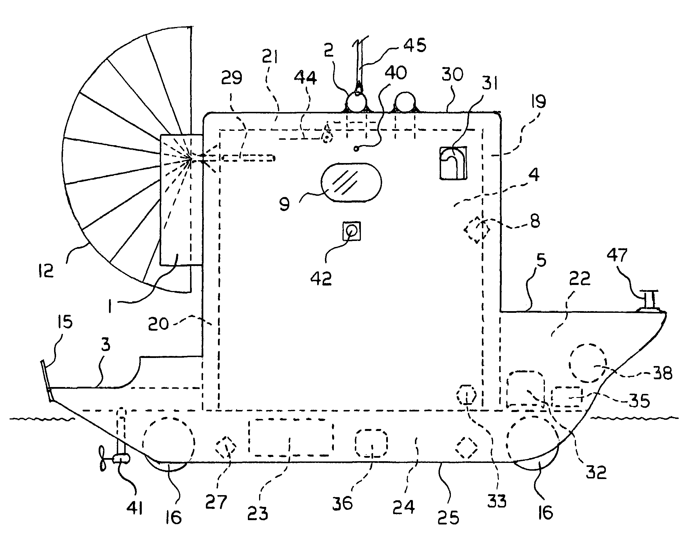
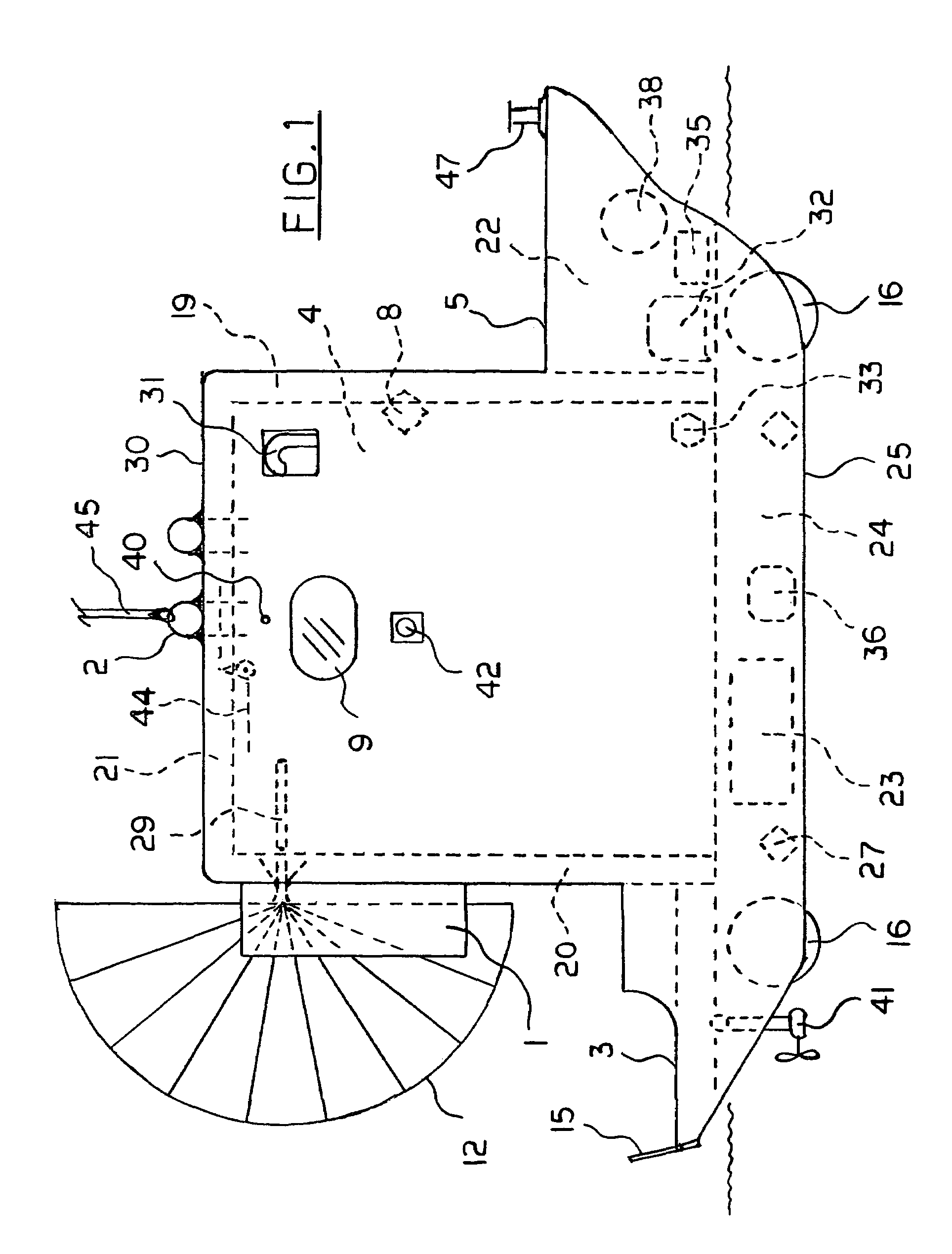
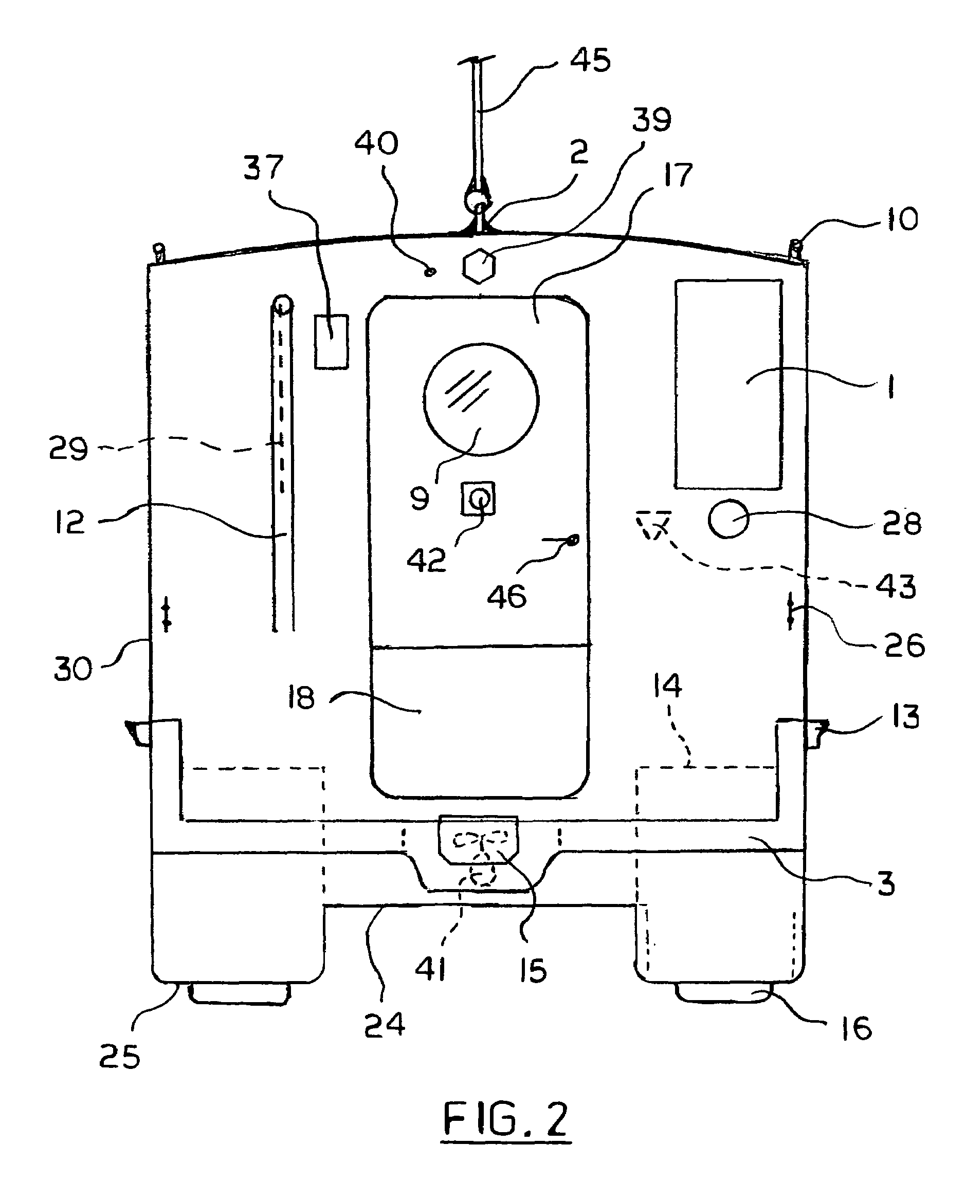
[0037]Referring to FIGS. 1, 2, 3 and 4, according to this invention, roof 21, front wall 19, two side walls 48 and rear wall 20 form an enclosed cabin 4 which is disposed on floor / hull 24. The cabin is framed with structural members and the exterior surface 30 is comprised of a rigid structural material attached to the framing members. The cabin is designed to withstand normal impact loads. This exterior structural material is weatherproof and provides structural integrity for the framed roof and walls. The Life Boot lifting and attachment devices are anchored to the framing members. A sponge / buoyant material in the cabin walls and roof provides insulation, floatation and occupant protection.

[0038]Floor / hull 24 functions as a floor in the cabin and as a sealed hull to operate in water. The floor / hull is streamlined to provide efficient water mobility and the contours of the floor / hull integrate with bow 22 and rear deck 3.

[0039]Main door 7 in the cabin is located in rear wall 20. Th...


PUM


Abstract

A multipurpose amphibious vehicle is configured with an enclosed cabin to protect occupants from impacts, hazardous environments, fire and extreme temperatures. The vehicle can be deployed from an aircraft with a parachute to remote areas for rescue, relief and security operations. A helicopter transports the vehicle by air with a single quick attachment / release device. The vehicle equipped with armor materials and gun ports, is used in hostile environments and protects occupants from chemical and biological weapons.

Description

[0001]The benefits under 35 U.S.C. 119 are claimed of provisional application 60 / 542,605 filed Feb. 6, 2004.FIELD OF THE INVENTION[0002]This invention relates to transporting personnel and equipment in an enclosed protected vehicle to provide support, rescue, security and transportation operations on the land, in the water, or in the air. The invention floats in water and electric power provides propulsion. On land, the invention rides on skids, a trailer, another motorized vehicle, or is self-propelled with electric powered wheels. In the air, the invention is airdropped from a plane or suspended from a helicopter. Equipped with a parachute device and a deceleration device, the invention can safely parachute for deployment or parachute down from a stricken helicopter.BACKGROUND OF THE INVENTION[0003]Existing rescue vehicles are typically self-propelled and specifically designed for land, sea, or air rescue. Current land rescue vehicles are often equipped with four-wheel drive; yet,...

Claims


Application Information

Patent Timeline
IPC IPC(8): B63H19/08
CPCB60F3/003
Inventor TALMAGE, JR., ROBERT N.
Owner TALMAGE JR ROBERT N
Learn More