Label application device

a technology of application device and label, which is applied in the direction of instruments, transportation and packaging, packaging, etc., to achieve the effect of reducing the influence of metal or liquid and ensuring secure transmission of information

Active Publication Date: 2006-10-12
SATO CO LTD
View PDF6 Cites 20 Cited by
  • Summary
  • Abstract
  • Description
  • Claims
  • Application Information

AI Technical Summary

Benefits of technology

[0029] With the label application device of the present invention, the folding and applying means enables a portion of the label on which the RFID tag is fixed to protrude to form an angle, so that when the label is applied to an article, the RFID tag can be separated from the article. Thus, when the material or content of the article to which the RFID tag is applied is metal or liquid, the influence of the metal or liquid can be reduced, whereby transmission of information can be performed securely.

Problems solved by technology

Incidentally, with a UHF RFID tag T in a label L which has been applied by such a conventional label application device, if the material or content of an article to which the label L is applied may disturb the electromagnetic wave, in other words, for example, if the material or content of the article contains metal, water, or the like, although depending on the frequency, a problem may occur because the electromagnetic wave is absorbed into the article due to the influence of the metal or the liquid such as water in the article, or a reader / writer cannot read or write the information of the IC chip Ta due to a disturbance in the electromagnetic wave caused by diffuse reflection.

Method used


Image

  • Label application device
  • Label application device
  • Label application device

Examples


first embodiment

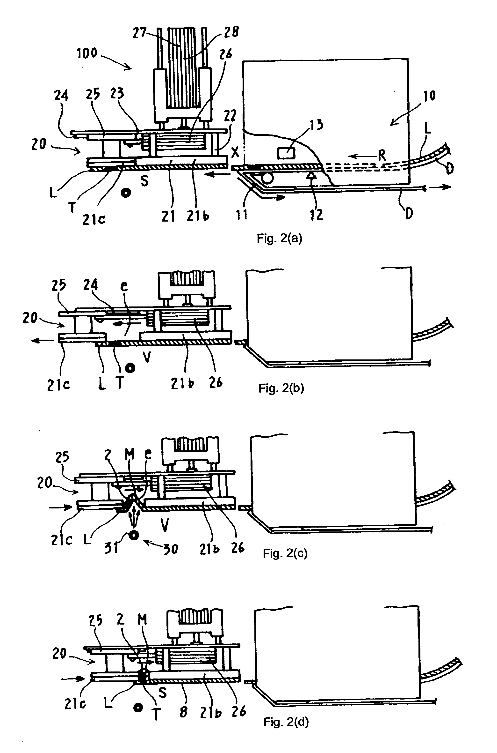
[0061] A label application device 100 in FIGS. 2 and 3 is operable to apply the label L to an article W which is conveyed along a predetermined conveyance direction from a conveyer C. The label application device 100 comprises label conveying means 10 and label folding and applying means 20.

[0062] The label conveying means 10 includes a release plate 11 operable for releasing the label L from the backing paper D, a sensor 12 for detecting that the label L has been conveyed to a predetermined position, and a reader / writer 13 for rewriting data to the IC chip Ta (FIG. 19) of the RFID tag T. The backing paper D tacked with the label L, which is supplied from a roller, not shown, is conveyed, and then folded back by the release plate 11, which separates the label L from the backing paper. The folded backing paper D is wound on a reel which is not shown.

[0063] Moreover, during conveying of the label L, the sensor 12 measures the timing for operating the folding and applying means 20, b...

second embodiment

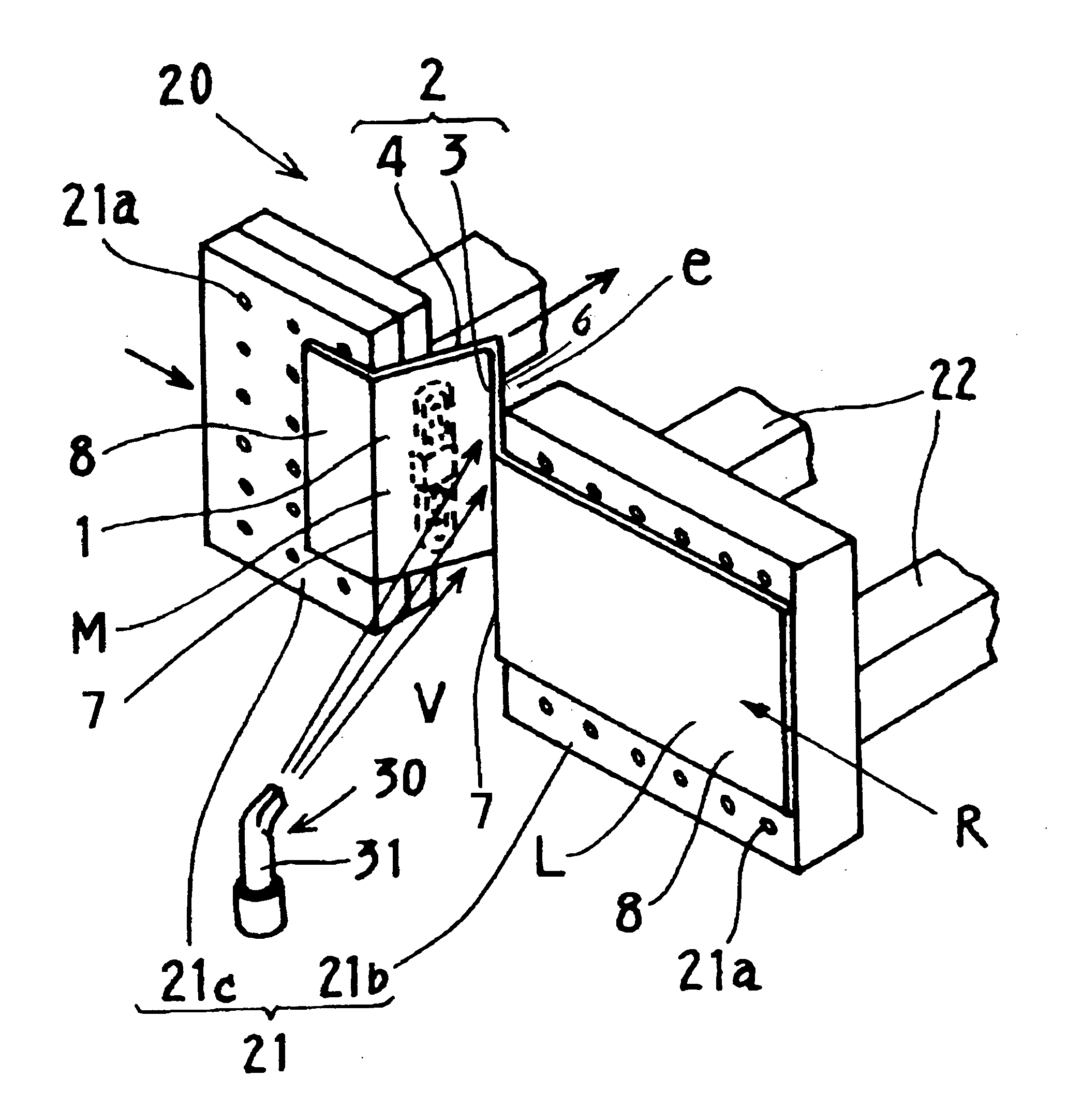
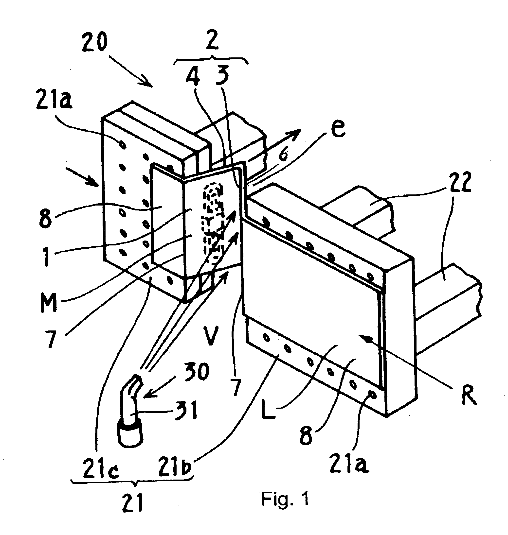
[0102]FIG. 9 through FIG. 11 show a label application device 200 according to the present invention. In the label L which is the object of the label application device according to the second invention, as shown in FIG. 4, FIG. 16 and FIG. 17, a portion 2 of the label L having the tag-fixing area 1 is formed in the intermediate or the generally middle portion of the label L.

[0103] The label application device 200 is configured the same as the label application device 100 according to the first embodiment, except that the structure of the fold assisting means 30 of the second embodiment differs from that of the label application device 100 of the first embodiment.

[0104] The fold assisting means 30 of the label application device 200 comprises a suction nozzle 32 which draws the portion 2 of the label L having the tag-fixing area 1 to which the RFID tag T of the label L is fixed, from the surface side (display layer U) of the portion 2, and folds the portion 2 of the label L toward t...

third embodiment

[0123] Therefore, as described hereinafter, the label L is applied by means of the label application device 300 according to the This section explains the situation when an operation flag is “ON” (1). When the operation flag is “OFF” (0), the label is applied flat in a similar fashion as described above.

[0124] As shown in FIG. 13(a), the label L is conveyed by the label conveying means 10, and when the backing paper D is folded by the release plate 11 and then the label L is released, the label L is attached to the attachment plate 41 and conveyed in the conveyance direction R of the label L. Then the label application control portion 92 operates the air cylinder device 47 to transfer the press member 46 from the separation position V to the joining position S. When the front end of the label L reaches the bearing portion 49 of the press member 46, the sensor 50 detects it and outputs a signal to the label application control portion 92. At the same time the label application contr...


PUM


Abstract

For applying a label to an article, and with a RFID tag on the label also being separated from the article, and for minimizing the influence from the article on the tag, and for securing stable reading and writing of data, a label application device applies a label to which a RFID tag comprising an IC chip and communication antenna is fixed, to the article. A folding device folds a portion of the label having a tag-fixing area to which the RFID tag is fixed, such that the back side of the label is pushed to the surface side of the label so that the label portion protrudes to form an angle and is folded, and then applying the label to the article. A device acts on the label portion to form the fold.

Description

1. CROSS-REFERENCE TO RELATED APPLICATION [0001] This application claims the benefit of the filing date of U.S. Provisional Patent Application No. 60 / 669,475 filed Apr. 8, 2005, the disclosure of which is hereby incorporated herein by reference.BACKGROUND OF THE INVENTION [0002] 1. Field of the Invention [0003] The present invention relates to a label application device for applying a label to an article, wherein the label is fixed with a so-called RFID tag having an IC chip therein for storing various information. [0004] 2. Description of the Related Art [0005] In a recent widely used technology, an IC (integrated circuit) chip for storing various information and a RFID (Radio Frequency Identification) tag comprising a communication antenna connected to the IC chip are together fixed inside a label which may be applied to various articles, to provide wireless, non-contact automatic identification by means of the RFID tag. [0006]FIG. 19 hereof shows a label L which is fixed with a R...

Claims


Application Information

Patent Timeline
Patent Type & Authority Applications(United States)
IPC IPC(8): G06F17/00
CPCB65C1/021B65C2009/0018B65C2009/0003B65C9/1884
Inventor HORN, KLAUSSCHWIERS, STEFANBARCZYK, VICTOR S.TOMOYUKI, KUMABAYASHI
Owner SATO CO LTD
Why Eureka
Try Eureka