Tolerance ring assembly

a technology of tolerance rings and assembly parts, applied in the direction of rod connections, instruments, physics instruments, etc., can solve the problems of increasing manufacturing costs, affecting the assembly quality of parts,

Active Publication Date: 2006-10-12
SAINT GOBAIN PERFORMANCE PLASTICS RENCOL
View PDF99 Cites 43 Cited by
  • Summary
  • Abstract
  • Description
  • Claims
  • Application Information

AI Technical Summary

Benefits of technology

[0018] An advantage of the present invention is correct assembly of a ring in a bore despite some axial misalignment of the ring and the bore.
[0019] The tolerance ring may be made of any suitable resilient material, preferably a metal, most preferably spring steel.
[0020] The guide portion may extend from the whole circumference of the band of the ring. Alternatively, the guide portion may extend from at least one segment of the circumference of the tolerance ring. The guide surfaces of the guide portion may be flared relative to the inside surface of the band of the tolerance ring. In one embodiment, the guide surface flares from the band to define an entrance at one end of the tolerance ring, wherein the perimeter or circumference of the entrance is greater than the circumference of the band of the tolerance ring. The guide portion provides a funnel extending from the band of the ring, with the guide surfaces angled relative to the axis of the band.
[0021]

Problems solved by technology

Improved engineering techniques have resulted in the need for greater accuracy of machine parts, raising manufacturing costs.
Problems can occur during assembly of parts that use tolerance rings.
As the tolerance ring requires a tight fit in the apparatus, there may be abrasion between the ring and various parts of the apparatus, which removes small fragments from the surface of the affected parts.
In certain apparatus, such as a computer hard disk drive where cleanliness is e

Method used


Image

  • Tolerance ring assembly
  • Tolerance ring assembly
  • Tolerance ring assembly

Examples


Embodiment Construction

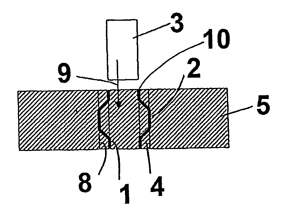
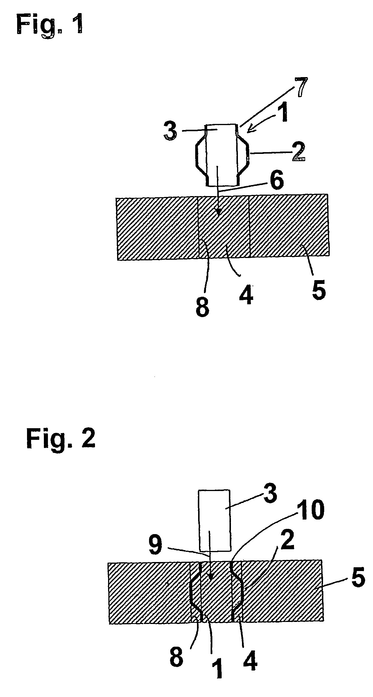
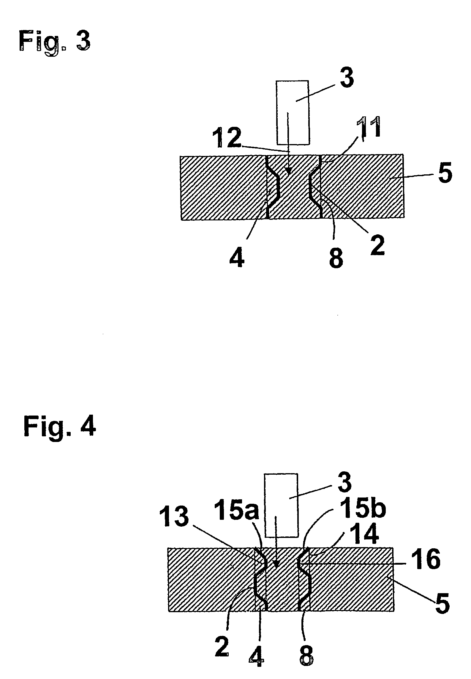
[0048] Before describing embodiments of the invention, it will be useful to understand conventional arrangements. Thus, FIGS. 1 to 3 illustrate use of a known tolerance ring to mount a shaft in a bore.

[0049] Thus, as shown in FIG. 1, a known tolerance ring with outwardly facing protrusions in the form of waves 2 and is fitted around a bearing 3 or bearing assembly 3 (hereinafter referred to as the bearing 3). The bearing 3 and tolerance ring 1 comprise a sub-assembly, which is axially inserted into the bore 4 of a body which may be an actuator arm 5 of a hard disk drive, indicated in FIG. 1 by the arrow 6. Unformed, annular portions 7 of the tolerance ring 1, which have no radial protrusions, axially flank the waves 2. Tolerance rings with outwardly facing protrusions are generally known in the art as S.V rings (Shaft Variable), as the diameter of the tolerance ring to be fitted to the bearing may be varied by differing amounts of overlap of the ends of the strip that forms the tol...


PUM

PropertyMeasurementUnit
Lengthaaaaaaaaaa
Circumferenceaaaaaaaaaa

Abstract

A tolerance ring has a band (16) with outwardly extending corrugated protrusions forming waves (2) which engage a surface (8) of the bore (4) in a housing (5). At one end of the tolerance ring is an outwardly flared guide surface (15a, 15b) extending axially from the band (16). The guide surface (15a, 15b) acts as an enlarged entrance to the band (16) for a shaft (3) to be mounted in the bore (4) by insertion into the tolerance ring. The use of the guide surface (15a, 15b) assists assembly and reduces or eliminates particle production. It is also possible for the corrugated portions to extend inwardly, for the guide surface to be inwardly flared, and for the tolerance ring to be mounted on the shaft prior to insertion in the bore.

Description

BACKGROUND OF THE INVENTION [0001] 1. Field of the Invention [0002] This invention relates to tolerance ring assemblies, wherein a tolerance ring provides an interference fit between parts of an assembly, where a first part has a cylindrical portion located in a cylindrical bore of a second part. The invention particularly relates to assemblies having a tolerance ring that provides an interference fit between a cylindrical component such as a shaft or a bearing and a housing for the shaft. [0003] 2. Summary of the Prior Art [0004] Improved engineering techniques have resulted in the need for greater accuracy of machine parts, raising manufacturing costs. Very close tolerances are required where press fits, splines, pins or keyways are employed to transmit torque in applications such as pulleys, flywheels or driveshafts. [0005] Tolerance rings may be used to provide an interference fit between parts required to transmit torque. Tolerance rings provide a low cost means of providing an...

Claims


Application Information

Patent Timeline
IPC IPC(8): F16B7/04F16C35/02F16C35/073F16C35/077F16D1/08G11B5/48G11B33/12
CPCF16C27/00F16C35/02F16C35/073F16C35/077F16D1/0835F16D2001/062Y10T403/7061G11B5/4813G11B25/043G11B33/12G11B33/123F16C2370/12Y10T403/7058G11B5/4806Y10T29/49696Y10T403/452Y10T403/453Y10T29/49945Y10T403/7047Y10T403/7049F16B2/241F16C43/00F16C35/07
Inventor WOODHEAD, NIKI S.SLAYNE, ANDREW R.
Owner SAINT GOBAIN PERFORMANCE PLASTICS RENCOL
Why Eureka
Try Eureka