
Single operator exchange embolic protection filter

Inactive Publication Date: 2006-10-12
BOSTON SCI SCIMED INC
View PDF99 Cites 20 Cited by
  • Summary
  • Abstract
  • Description
  • Claims
  • Application Information

AI Technical Summary

Benefits of technology

[0009] In another embodiment, the current invention can include a stylet. The stylet has a distal end and a proximal end, and the distal end can be shaped in order to make it easy to grasp. The stylet can be fed through the distal guidewire lumen and can exit the proximal side of the filter body. Thus, as the filter assembly is fed into the containment lumen, the filter wire can be fed into the first lumen and the proximal end of the stylet can be fed into the second or third lume

Problems solved by technology

During interventional vascular procedures such as angioplasty, atherectomy, thrombectomy and stenting, access to the lesion is often difficult due to the tortuous nature of the vasculature.

Method used


Image

  • Single operator exchange embolic protection filter
  • Single operator exchange embolic protection filter
  • Single operator exchange embolic protection filter

Examples


Embodiment Construction

[0029] The following description should be read with reference to the drawings, in which like elements in different drawings are numbered in like fashion. The drawings, which are not necessarily to scale, depict selected embodiments and are not intended to limit the scope of the invention. Although examples of construction, dimensions, materials and manufacturing processes are illustrated for the various elements, those skilled in the art will recognize that many of the examples provided have suitable alternatives that may be utilized.

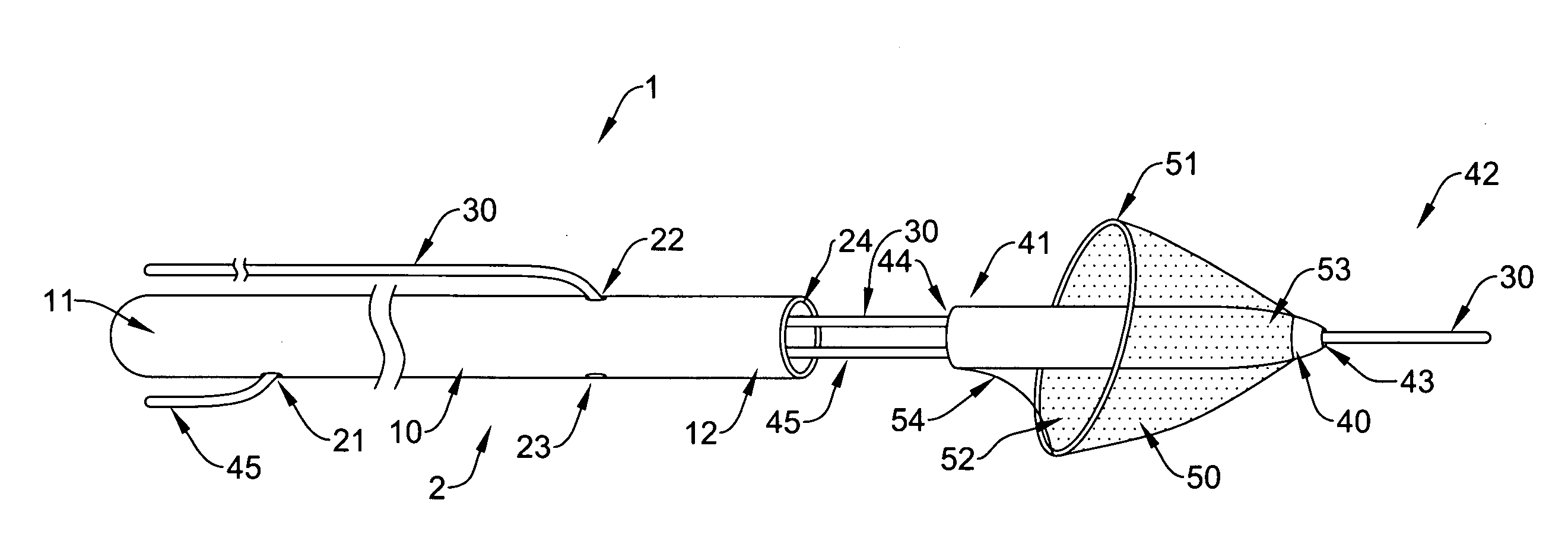
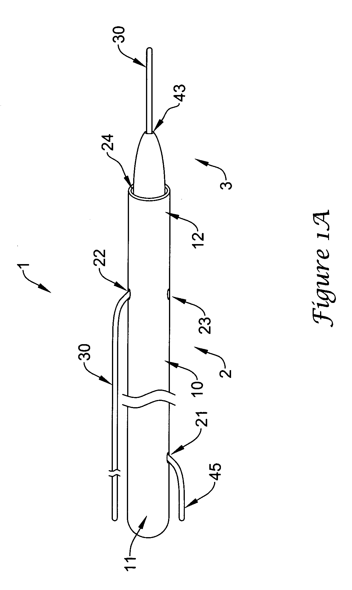
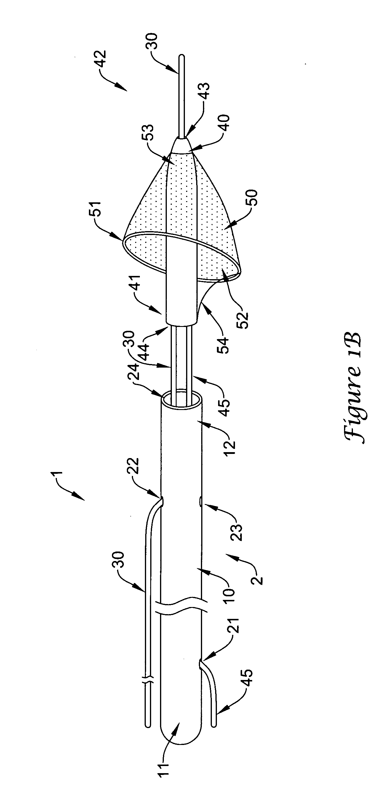
[0030]FIG. 1A is a perspective view of a device 1 for deploying intravascular devices, such as embolic filters. The device 1 comprises a delivery system 2 and a filter assembly 3. The delivery system 2 comprises an elongate member 10, which has a distal end 12 and a proximal end 11. The elongate member 10 further comprises a filter wire port 21, a first guidewire port 22 and a second guidewire port 23. The distal end of the elongate member also define...


PUM


Abstract

Systems and methods for transporting and deploying intravascular devices through a body lumen are disclosed. An intracorporeal device in accordance with an exemplary embodiment of the present invention can include an elongate member with a proximal portion defining first, second and third lumens and a distal portion defining a containment lumen. A filter assembly can be disposed within the containment lumen, with a filter wire attached to the filter assembly and extending through the first lumen. A guidewire can be passed through a distal guidewire lumen that extends through the filter assembly. The guidewire can extend through the distal guidewire lumen and through the second or third lumen. With the filter assembly disposed in the elongate member, the guidewire can then be advanced through a patient's vasculature, the filter delivery system advanced through the vasculature over the guidewire and the filter assembly deployed from the containment lumen.

Description

FIELD OF THE INVENTION [0001] The present invention relates generally to the field of intracorporeal devices. More specifically, the present invention pertains to systems and methods for transporting and exchanging intravascular devices such as embolic filters within a body lumen. BACKGROUND OF THE INVENTION [0002] Guidewires are frequently used to advance intravascular devices to various locations within the body such as an artery or vein. Examples of therapeutic procedures employing such devices include percutaneous transluminal coronary angioplasty (PTCA), percutaneous extraction atherectomy, and stent placement. In a PTCA procedure, for example, a guidewire is percutaneously inserted into a patient's body, and then advanced to a target site where a stenosis or other occlusion is located. Once in place, an angioplasty catheter having an inflatable balloon is advanced along the guidewire and positioned across the site of the stenosis to be dilated. The inflatable balloon is then i...

Claims


Application Information

Patent Timeline
IPC IPC(8): A61M29/00
CPCA61F2/013A61F2002/015A61F2230/0008A61F2002/018A61F2230/008A61F2/011
Inventor WASICEK, LAWRENCE D.RENATI, RICHARD J.
Owner BOSTON SCI SCIMED INC
Learn More