Cover structure for buggy vehicle

a technology for vehicle covers and buggy vehicles, applied in the field of buggy vehicles, can solve the problems of unsatisfactory assembly of the body cover to the body frame, and also unsatisfactory maintenance performance, so as to improve the assembling work and the maintenance performance of the power unit. , the effect of enhancing the external appearan

Active Publication Date: 2006-10-19
HONDA MOTOR CO LTD
View PDF10 Cites 10 Cited by
  • Summary
  • Abstract
  • Description
  • Claims
  • Application Information

AI Technical Summary

Benefits of technology

[0014] In view of the foregoing, the present invention has been made and it is an object of an embodiment of the present invention to provide a cover structure for a buggy vehic

Problems solved by technology

Since the overall body cover is formed integrally in the conventional buggy vehicle, the assembling of the body cover to the body frame is unsatisfactor

Method used


Image

  • Cover structure for buggy vehicle
  • Cover structure for buggy vehicle
  • Cover structure for buggy vehicle

Examples


Embodiment Construction

[0066] One embodiment of the present invention will be described below with reference to the accompanying drawings.

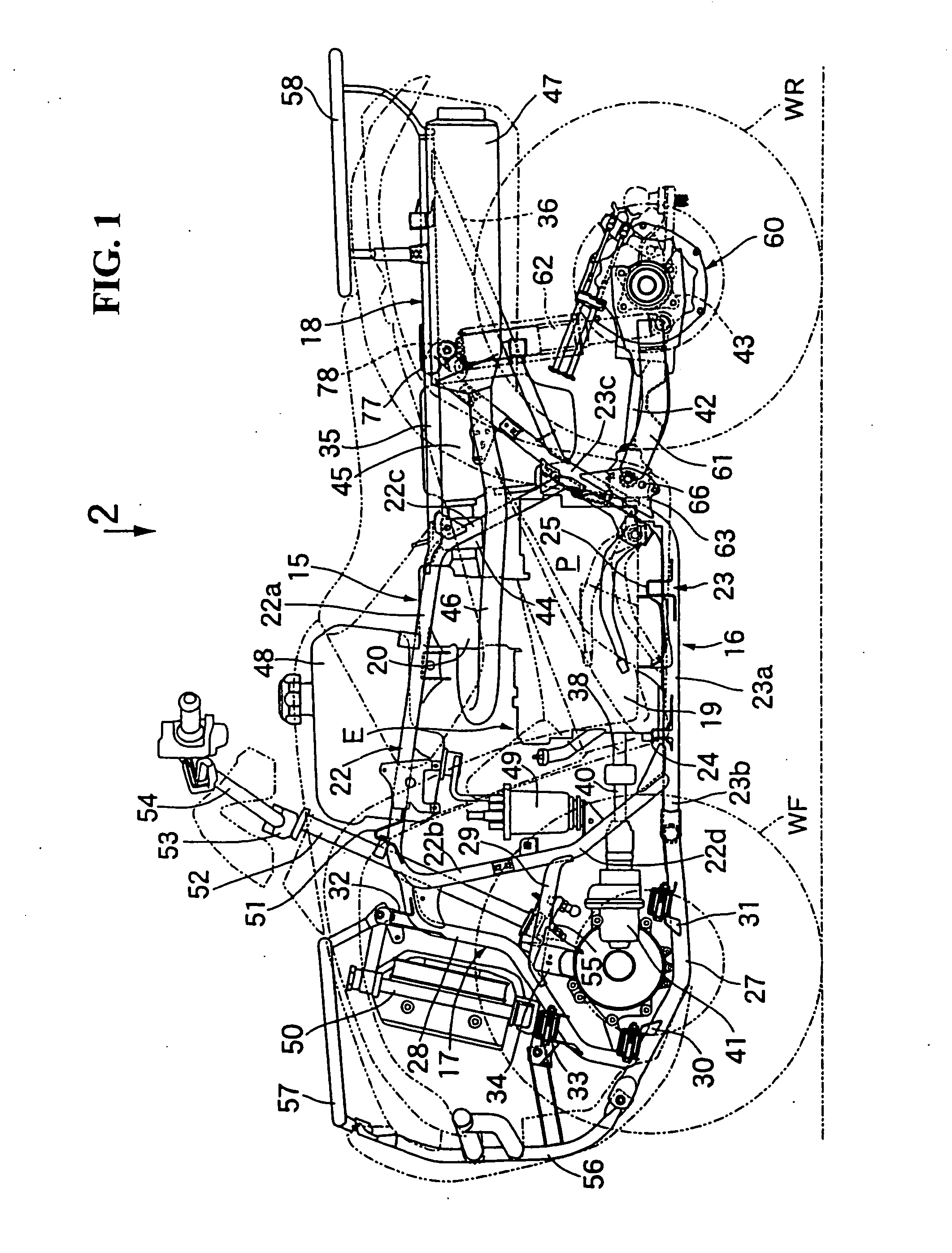
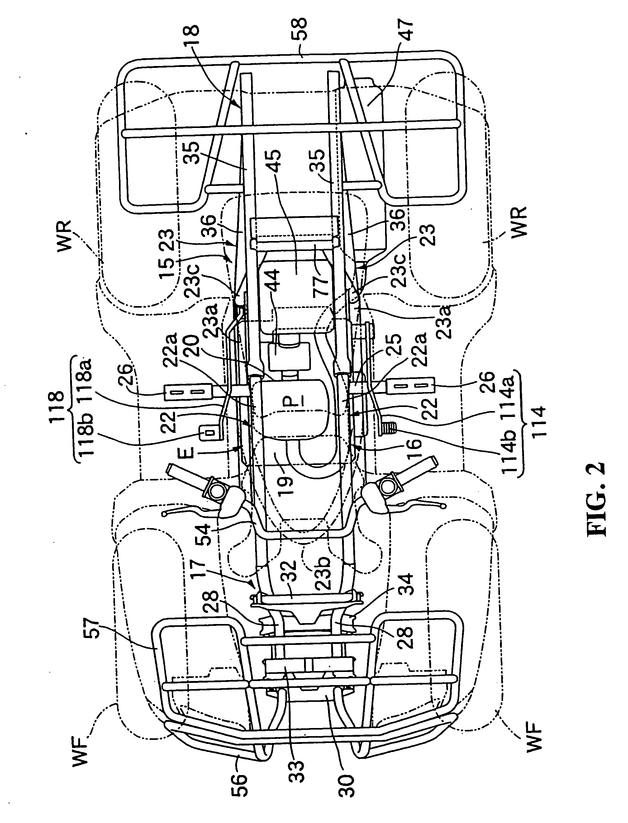
[0067] Referring first to FIGS. 1 and 2, the buggy vehicle is an all terrain vehicle which mainly enhances drivability on irregular ground. The vehicle includes a pair of left and right front wheels WF and a pair of left and right rear wheels WR both suspended by the front portion and rear portion, respectively, of a body frame 15. The front wheel WF has a low pressure balloon tire with a relatively large diameter attached thereto and the rear wheel WR has a low pressure balloon tire with a relatively small diameter attached thereto.

[0068] The body frame 15 is composed of multiple kinds of steel products that are joined together by welding or the like and includes a center frame 16, a front frame 17 and a rear frame 18. The front frame 16 mounts thereon a power unit P including an engine E and a transmission (not shown) incorporated in the crankcase 19 of the engine E...


PUM


Abstract

A body cover being formed by joining together a plurality of cover members including a maintenance cover which is detachably disposed on the side of the power unit. A pedal which is actuated by an individual operating the vehicle wherein the overall body frame is covered without modifying the structure and arrangement of the pedal. A suspension system wherein a swing arm type or an independent suspension type may be used in the vehicle. A light structure for a tail light wherein attaching lighting components such as a light emitting section are attached to a substrate formed in part of a lid of a utility box attached to a rear part of a vehicle. The lighting components such as the substrate are directly assembled in the concave section, and a lens is attached to the concave section by welding.

Description

CROSS-REFERENCE TO RELATED APPLICATIONS [0001] The present application claims priority under 35 USC 119 to Japanese Patent Application Nos. 2005-171969; 2005-171967 and 2005-171968 filed on Jun. 13, 2005 and 2005-094497 filed Mar. 29, 2005 the entire contents of which are hereby incorporated by reference. FIELD OF THE INVENTION [0002] The present invention relates to a buggy vehicle in which a power unit, a fuel tank disposed above the power unit and an air cleaner disposed rearwardlyly of the power unit are mounted on a body frame. An operator seat is disposed rearwardly of the fuel tank and above the air cleaner. Step boards are disposed on both sides of the power unit in such a manner so that an operator positioned on the seat places her or his feet thereon. In particular, the invention relates to improvement of a cover structure. The present invention relates to a light structure and light attachment method for a light for a vehicle attached to a vehicle such as, for example an ...

Claims


Application Information

Patent Timeline
IPC IPC(8): B62D31/00
CPCB62K5/01
Inventor TAKAHASHI, SHINJISHIMIZU, KENZOHANAFUSA, SEIJIYAMAMOTO, TAKAO
Owner HONDA MOTOR CO LTD
Why Eureka
Try Eureka