Fuel injection device for internal combustion engine

a fuel injection device and internal combustion engine technology, which is applied in the direction of electric control, machines/engines, vehicle maintenance, etc., can solve the problems of affecting may eventually be damaged, and achieve the effects of improving the reliability of the piezo stack, enhancing the reliability of the fuel injection device, and increasing the durability of the piezo injector

Inactive Publication Date: 2006-10-19
DENSO CORP +2
View PDF5 Cites 13 Cited by
  • Summary
  • Abstract
  • Description
  • Claims
  • Application Information

AI Technical Summary

Benefits of technology

[0035] In the 18th mode of the present invention, a resilient member for applying a compressing force to the piezo stack is provided between the piezo stack and the fixed member which accepts the expansion of the piezo stack at the end opposite from the driving member. By thus disposing the resilient member for applying a compressing force to the piezo stack, if a contraction causing an abrupt drop in the applied load occurs during the charging to the ...

Problems solved by technology

As a result, in the case of the piezo injector having a structure in which a driving member is pressed against the piezo stack, contraction and expansion repetitively occur in the piezo stack at every combined reso...

Method used


Image

  • Fuel injection device for internal combustion engine
  • Fuel injection device for internal combustion engine
  • Fuel injection device for internal combustion engine

Examples


first embodiment

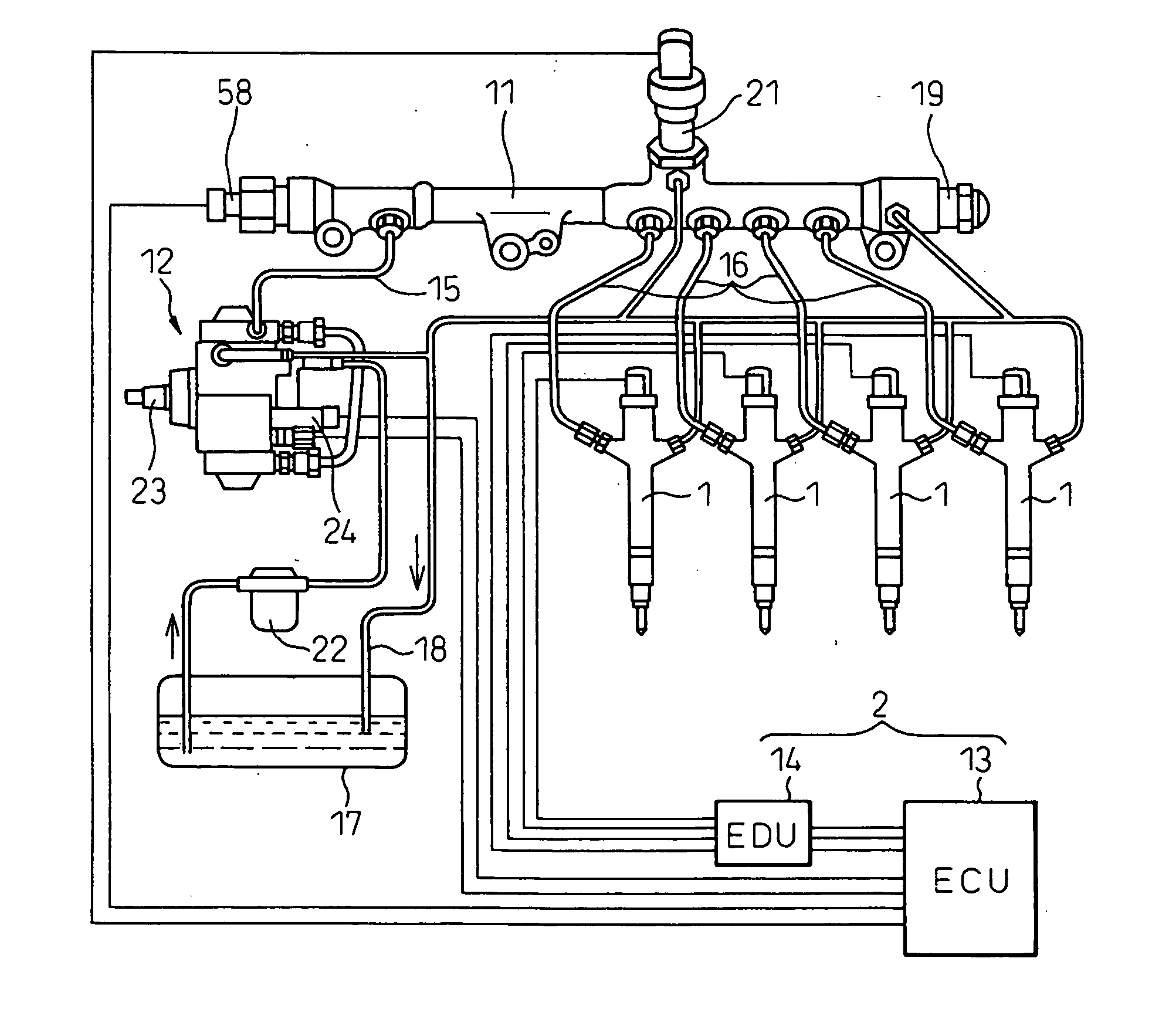
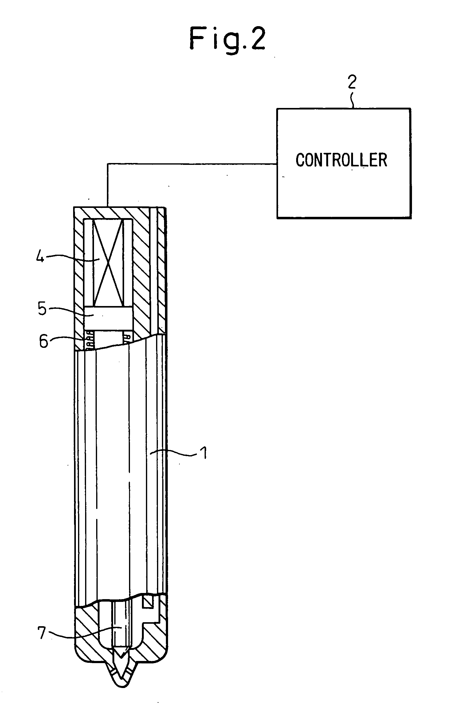
[0088] A first embodiment of the present invention will be described below with reference to FIGS. 1B to 9. First, the basic configuration of the fuel injection device will be described with reference toFIG. 2. The fuel injection device comprises a piezo injector 1 to which fuel is supplied from the outside, and a controller 2 which controls the operation of the piezo injector 1.

[0089] The piezo injector 1 comprises a piezo stack 4 constructed from a stack of piezo elements 3 (see FIG. 6) which, when electrically charged, generates an expansion in the stacking direction, and a driving member 5 which moves in the stacking direction by being directly driven with the expansion of the piezo stack, and the piezo injector 1 performs fuel injection by causing the driving member 5 to move in the stacking direction. The piezo injector 1 is provided with a first return spring 6 which compresses the piezo stack 4 via the driving member 5, the structure being such that the instant the piezo st...

second embodiment

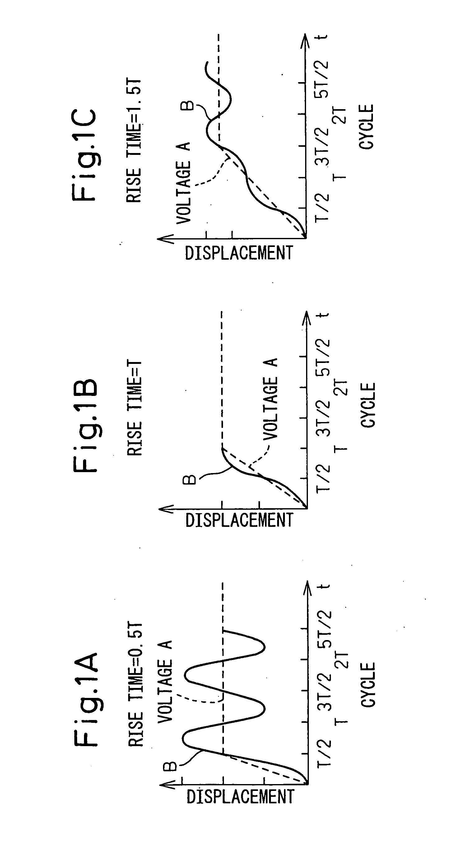
[0144] A second embodiment according to the present invention will be described below with reference to FIGS. 10A and 10B. In each embodiment hereinafter given, the same reference characters as those in the first embodiment indicate parts having the same functions. The first embodiment described above has shown examples in which the expansion and contraction force occurring after the charge voltage has reached the target charge voltage are suppressed by making the voltage rise time t equal to or longer than 0.6T. In contrast, the second embodiment aims to suppress the expansion and contraction force occurring after the charge voltage has reached the target charge voltage, even when the voltage rise time t is shorter than 0.6 T.

[0145] The controller 2 of the second embodiment performs second voltage rise control in which, when 0.25 T≦t<0.6T, the average voltage rise speed during the period from 0.5 t to 1 t is made slower than the average voltage rise speed during the period from th...

third embodiment

[0151] A third embodiment according to the present invention will be described below with reference to FIGS. 11 and 12. The piezo stack 4 and the driving member 5 are subjected to external loads such as friction during expansion. When the charging is started, the piezo stack 4 begins to generate an expansion load. After the piezo stack 4 begins to expand, the expansion load reaches a maximum the instant the driving member 5 begins to move. To describe a specific example with reference to FIG. 11, a load variation peak occurs in the piezo stack 4 at a time instant 21 (μs) after the initiation of the charging to the piezo stack 4. Immediately after the occurrence of the load variation peak, a contraction occurs in the direction in which the expansion contracts; thereafter, dips and peaks due to overshooting occur repetitively. As such expansion and contraction force are applied directly to the piezo stack 4, the piezo stack 4 may eventually be damaged.

[0152] The fuel injection device...


PUM


Abstract

A fuel injection device wherein when the combined natural resonant period of a piezo stack and a driving member constituting part of a piezo injector of a fuel injection device is denoted by T, and the voltage rise time taken from the moment the charging to the piezo stack is initiated until the piezo stack is charged to a target charge voltage is denoted by t, then, in order to prevent oscillating loads from being applied to the piezo stack after elapse of the voltage rise time t when t≦0.5 T±0.1 T, the voltage rise time t that satisfies the relation 0.6T≦t is set in a controller for the piezo injector and, thus, the voltage rise slope of the piezo stack immediately before reaching the end of the voltage rise time t is made gentler to suppress the expansion and contraction force occurring in the piezo stack and thereby enhance the long-term reliability of the piezo stack.

Description

CROSS-REFERENCE TO RELATED APPLICATION [0001] This application claims priority from, and incorporates by reference the entire disclosure of, Japanese Patent Applications No. 2005-118599, filed on Apr. 15, 2005, and No. 2005-166048, filed on Jun. 6, 2005. BACKGROUND OF THE INVENTION [0002] 1. Field of the Invention [0003] The present invention relates to a fuel injection device for an internal combustion engine equipped with a piezo injector which controls fuel injection by an expansion that a piezo stack comprising a stack of piezo elements generates and, more particularly, to a fuel injection device for an internal combustion engine to which a technique for enhancing the reliability of the piezo stack is applied. Hereinafter, the internal combustion engine will be referred to simply as the engine. [0004] 2. Description of the Related Art [0005] A piezo stack constructed by stacking piezo elements generates an expansion by expanding in the stacking direction when every piezo element...

Claims


Application Information

Patent Timeline
IPC IPC(8): B60S9/21
CPCF02D41/2096F02D2041/2024F02M51/0603F02D2200/0602F02D2041/2051
Inventor FUJII, AKIRAHISHINUMA, OSAMUARIKAWA, FUMIAKITAKAHASHI, IZUMIKIYAMA, AKIRA
Owner DENSO CORP
Why Eureka
Try Eureka