Catch basin apparatus and method of use for the same

a technology of catch basin and apparatus, which is applied in the direction of sedimentation settling tank, separation process, filtration separation, etc., can solve the problems that the type of system has yet to adequately address the management of problems, and achieve the effect of improving the efficiency of the conventional sewer system and enhancing industrial efficiency

Inactive Publication Date: 2006-10-19
MARZETT WAYLAND +1
View PDF34 Cites 19 Cited by
  • Summary
  • Abstract
  • Description
  • Claims
  • Application Information

AI Technical Summary

Benefits of technology

[0005] For example, by using the combination of at least one diverter and a sieve-member or element to divide a primary and at least a secondary collection area, the present disclosure overcomes the longstanding need to be able to get between, behind under or in back of the sieve-member or element and remove debris and detritus by way of a specialized aperture permitting ingress and egress.
[0006] The present disclosure manages the issue of having a continuous flow-path while being able to stem the flow of large pieces of debris, and being able to render those pieces which may become lodged readily removable. This is done in straight-forward fashion, enabling those charged with removing potentially clogging pieces of debris to have ready access to the area proximate to the drain which is at the bottom of the system.
[0007] Likewise, those skilled in the art shall understand that such improved catch basin technology overcomes the longstanding issues associated with spaces too small for workers to reach into to remove pieces of debris which become difficultly lodged. An additional aspect of the present disclosure is that it does not require further attachments, assemblies or supplemental pieces at the ingress, or for example, at the “curb” in a conventional city-type of sewer inlet. This feature is useful and enhances industrial efficiency.
[0008] According to the teachings of the instant disclosure, the efficiency of a conventional sewer system is further improved in that the enhancements to the catch basis render the system such that it does not need to be manually monitored or emptied with as high a degree of frequency. Owing to the simple mechanical aspects of functionality of the instant disclosure the involved materials can be both strong and robust in addition to being acquired without tremendous capital outlay.
[0009] Further, since many conventional, for example, metropolitan sewer systems, have many different locations needing to be improved, ready installation capacity, ease-of-use and transport make the teachings of the present disclosure attractive to users. It is also known to artisans how the solution offered by the instant teachings can have a “universal” aspect, if it functions in conjunction with or is readily adaptable to many different related types of systems.
[0010] Finally, owing to the modularity of the components according to the instant teachings plethoric combinations and subcombinations are available. For example, for use with conventional metropolitan sewer systems those having a modicum of skill shall understand that at least one diverter is easily curb-mounted with most existing systems, as is a sieve member or element combination. Being modular provides for easy and facile transport, shipping, storage and related conveniences.

Problems solved by technology

Combinations of these two usually distinct types of systems have yet to adequately address the issues managed by way of the present disclosure.

Method used


Image

  • Catch basin apparatus and method of use for the same
  • Catch basin apparatus and method of use for the same
  • Catch basin apparatus and method of use for the same

Examples


Embodiment Construction

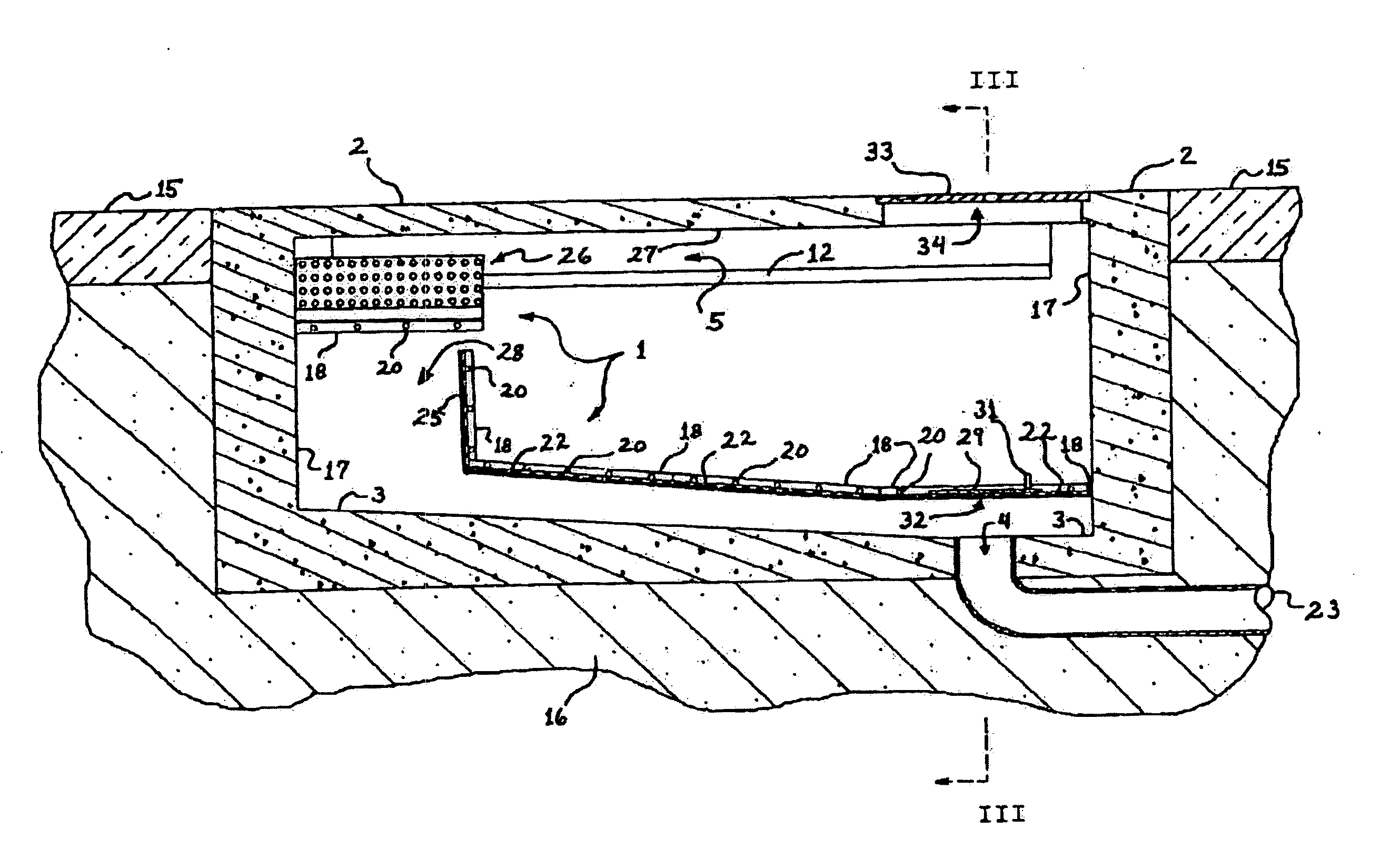
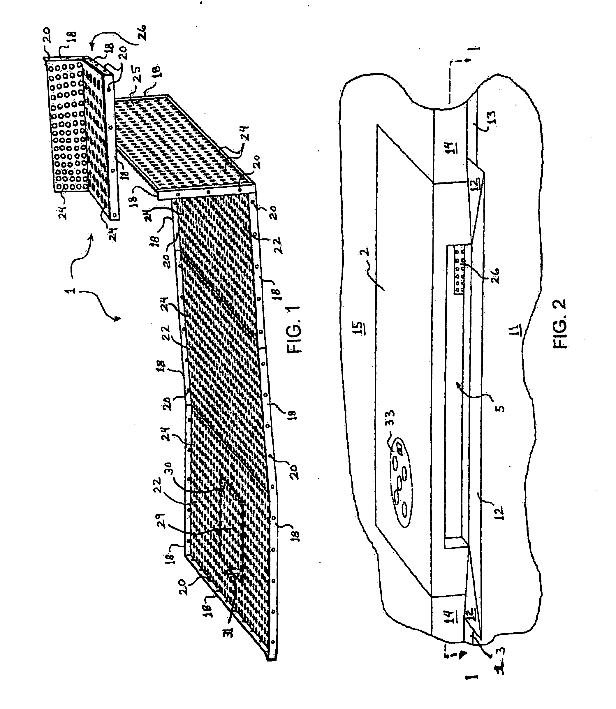
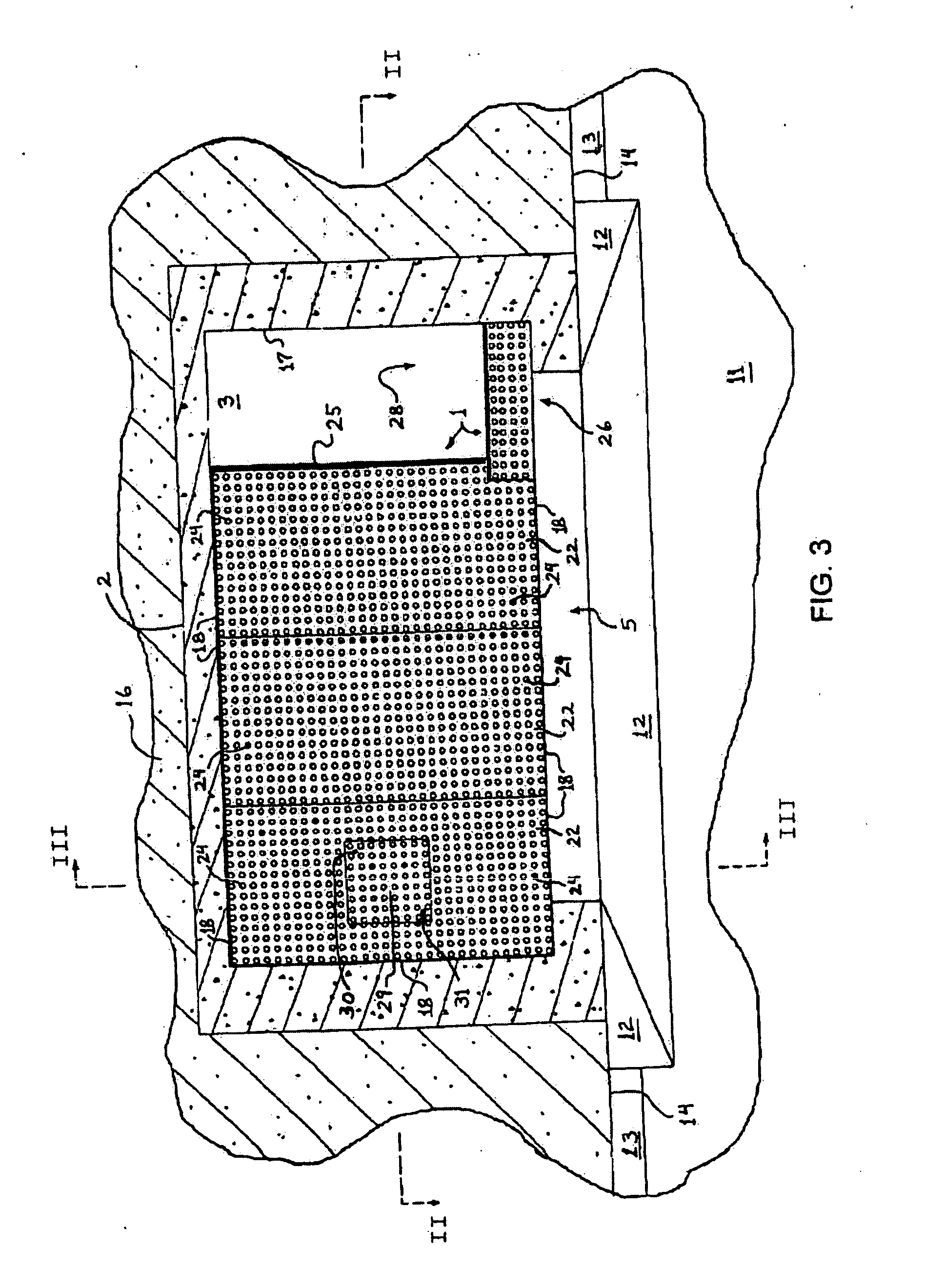
[0024] Referring to the drawings, FIGS. 1-6 show one embodiment, referred to herein as a left-drain filter 1, as it would appear in an installation configuration but (as illustrated in FIG. 1) without being installed in any catch basin and (as illustrated in FIGS. 2-6) after being installed into a left-drain catch basin 2. The left-drain filter 1 is configured for installation into the left-drain catch basin 2, which has a floor 3 and a drain opening 4 in the left portion of the floor 3. The left-drain catch basin 2 is designed to allow fluid to enter through a curb-inlet opening 5 and to exit through the drain opening 4 located in the left portion of the catch basin.

[0025]FIGS. 7-9 show another embodiment, referred to herein as a center-drain filter 6, as it would appear in its installation configuration but (as illustrated in FIG. 7) without being installed in any catch basis and (as illustrated in FIGS. 8-9) after being installed into a center-drain catch basin 7, which is desig...


PUM

PropertyMeasurementUnit
areaaaaaaaaaaa
sizeaaaaaaaaaa
dimensionsaaaaaaaaaa

Abstract

Apparatus for optimizing fluid flow while maximizing selective filtration of select debris and detritus functions as catch basin in conjunction with conventional sewers. Proximate to a curb inlet a diverter is located, and at least one sieve-member or element is disposed within the catch basin defining a primary and supplemental space for collecting solid materials, in combination with a drain access aperture allowing for ingress and egress to the supplemental space from the primary space to preclude blockage by facilitating access to the catch basin drain.

Description

FIELD OF THE DISCLOSURE [0001] The present disclosure generally relates to novel catch basin constructions used in a sewer-type of apparatus which cost effectively make cleaning of the same easier, while being disposed simply without adding cost or time constraints. [0002] The present disclosure further relates to catch basin improvements allowing for ongoing flow while selectively screening undesired elements from transmission to a drain. BACKGROUND OF THE DISCLOSURE [0003] Filtration systems have been known throughout history for blocking ingress and egress selectively. Sewer systems and their related drains are a product of modern society, often having a need to be disposed within, for example, city streets in a metropolitan area. Combinations of these two usually distinct types of systems have yet to adequately address the issues managed by way of the present disclosure. SUMMARY [0004] The present disclosure works in conjunction with conventional drainage systems, for example, s...

Claims


Application Information

Patent Timeline
Patent Type & Authority Applications(United States)
IPC IPC(8): E03F5/14E03F5/16
CPCB01D21/0006B01D21/0012E03F5/14E03F5/0404E03F5/0401
Inventor MARZETT, WAYLANDNINO, KHALIL IBRAHIM
Owner MARZETT WAYLAND
Why Eureka
Try Eureka