Pipe clamping device

a clamping device and pipe technology, applied in the direction of hose connection, fluid pressure sealed joint, sleeve/socket joint, etc., can solve the problems of large appearance of the clamping device, difficult connection and disconnect of pipes with and from the clamping ring, and large clamping force required in fitting the clamping ring, etc., to achieve easy insertion and assembly, increase the effect of bite strength and strong grip of pipes

Inactive Publication Date: 2006-10-19
KWAK BYUNG WOON
View PDF7 Cites 12 Cited by
  • Summary
  • Abstract
  • Description
  • Claims
  • Application Information

AI Technical Summary

Benefits of technology

[0011] To solve the above problems, it is an object of the present invention to provide a pipe clamping device in which a pipe can be easily inserted into and assembled with a clamp ring during an assembly, and after assembly, when a female bracket is screw-tightened with a male bracket,

Problems solved by technology

However, a compulsive engagement work which is performed by inserting pipes into a conventional clamp ring having a small amount of elastic deform and forcedly biting and fixing the pipes with and to the clamp ring with a sufficient gripping force, requires much force in fitting the clamp ring having a narrow entrance diameter with the pipes.
Accordingly, it is very difficult to connect and disconnect pipes with and from the clamp ring.
Thus, the external appearance of the clamping device becomes large and a manufacturing cost is increased.
Also, since the conventional

Method used


Image

  • Pipe clamping device
  • Pipe clamping device
  • Pipe clamping device

Examples


Embodiment Construction

[0027] Hereinbelow, a pipe clamping device according to preferred embodiments of the present invention will be described with reference to the accompanying drawings.

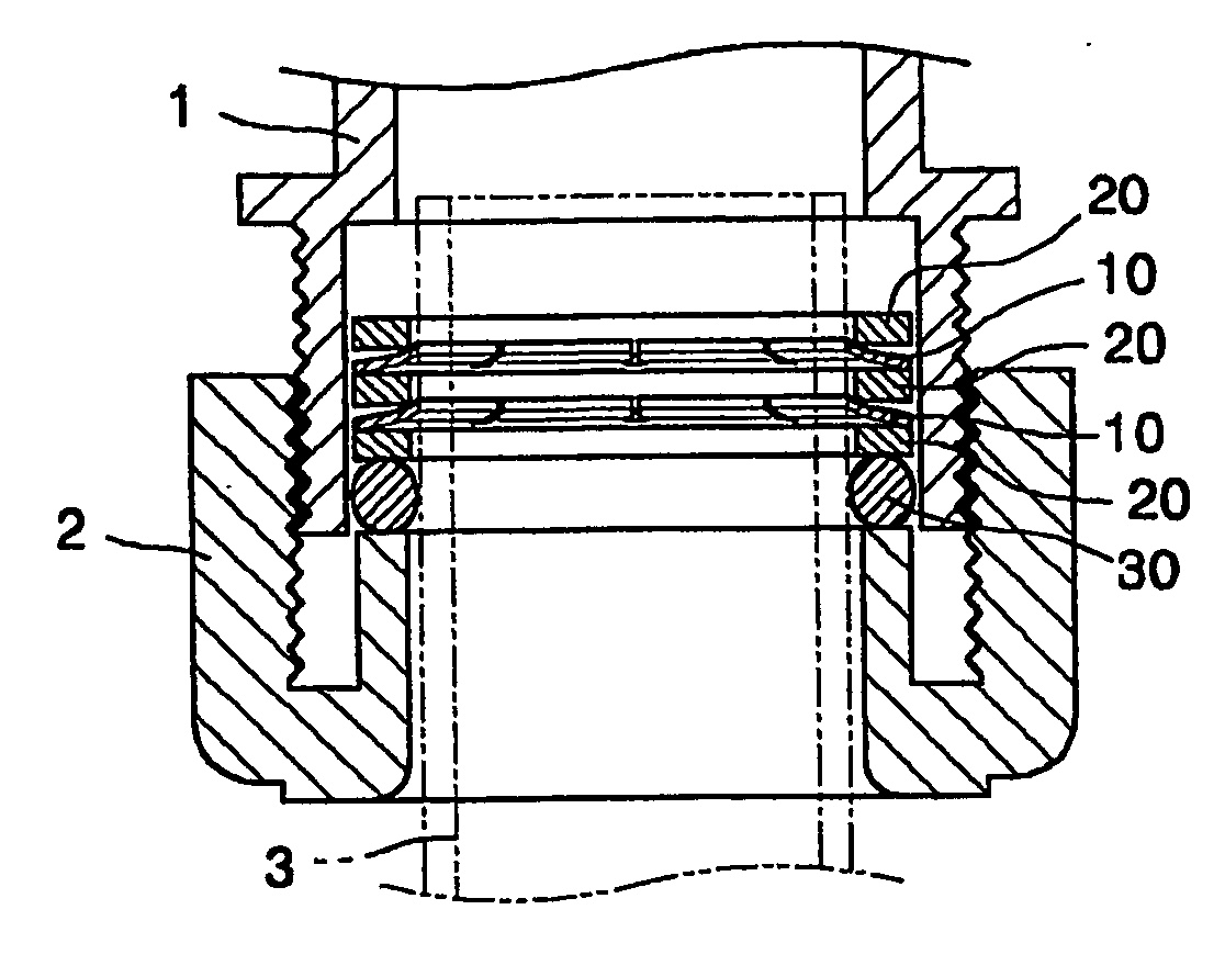
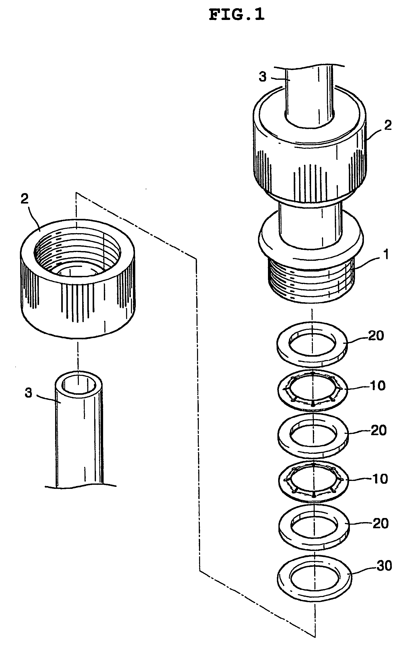
[0028] First, as shown in FIG. 1, a pipe clamping device according to a preferred embodiment of the present invention is installed between a female bracket 1 and a male bracket 2 which are coupled with each other, in order to clamp a pipe 3. The pipe clamping device includes a clamp ring 10 which clamps the pipe 3, a pressure ring 20 which pressurizes the clamp ring 10 so that the entrance of the clamp ring 10 is narrowed, and an O-ring 30 which seals the pipe 3.

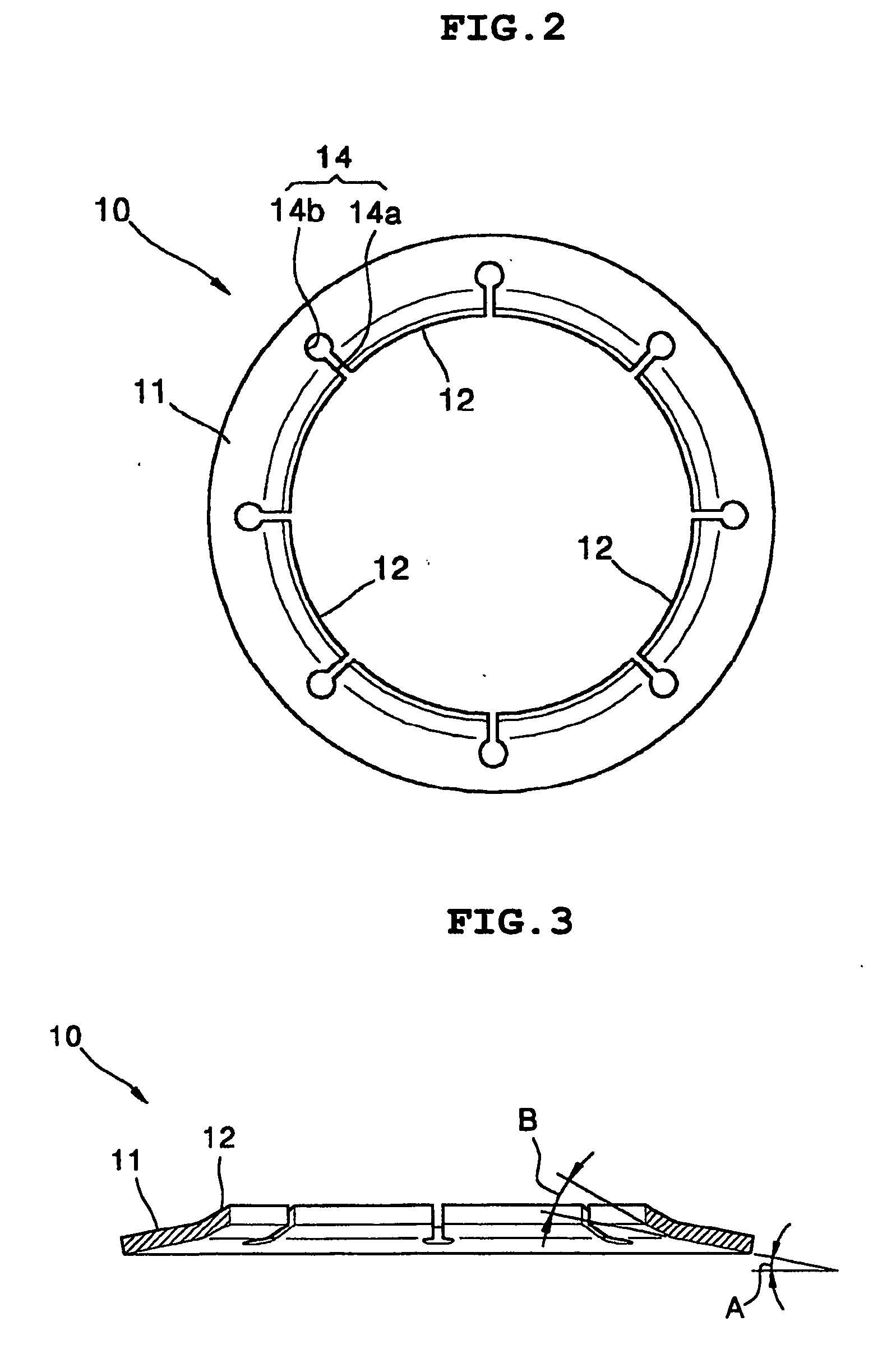
[0029] That is, as shown in FIG. 2, the clamp ring 10 is installed between the female bracket 1 and the male bracket 2. A blade 12 which grips the outer circumference of the pipe 3 and fixes the pipe 3, is formed in the inner circumference of the clamp ring 10, and is made of an elastic material so as to be deformed with a predetermined displacement. Further, t...


PUM


Abstract

A pipe clamping device having a stronger gripping force by an elastic deform of a clamp ring during screw-tightening is provided. The pipe clamping device includes at least one clamp ring installed between a female bracket and a male bracket, and made of an elastic material to have a predetermined deform, pressure rings installed in the upper and lower portions of the clamp ring, respectively, and an O-ring formed between the pressure ring and the female bracket and pressurizes the pressure rings to closely contact and seal the pipe. Accordingly a pipe can be easily inserted into and assembled with the clamp ring during an assembly. After assembly, when the female bracket is screw-tightened with the male bracket, the entrance of the blade is narrowed and thus the inner diameter of the clamp ring is also narrowed.

Description

TECHNICAL FIELD [0001] The present invention relates to a pipe clamping device, and more particularly, to a pipe clamping device having a stronger gripping force by an elastic deform of a clamp ring during screw-tightening. BACKGROUND ART [0002] In general, when a pipe and another pipe are connected with each other, a pipe clamping device which bites and fixes pipes is widely used in order to combine the pipes with each other strongly without leaking internal fluid from the pipes. [0003] A conventional pipe clamping device includes a clamp ring which is installed between a female bracket and a male bracket which are screw-tightened with each other, and which is formed of a simplified metal ring shape in which a blade of the clamp ring bites the outer circumferences of pipes in order to prevent the pipes from seceding, and an O-ring which seals a gap between the pipes bitten by the clamp ring. [0004] Here, the clamp ring is forcedly engaged with the pipes, and the blade of the clamp ...

Claims


Application Information

Patent Timeline
IPC IPC(8): F16L19/08F16L37/091
CPCF16L37/091F16L19/086F16L19/08
Inventor KWAK, BYUNG-WOON
Owner KWAK BYUNG WOON
Why Eureka
Try Eureka