Driving mechanism, photographic mechanism and cellular phone
a driving mechanism and a technology of a cellular phone, applied in the direction of printers, instruments, camera focusing arrangement, etc., can solve the problems of displacement of a driving member in a direction, vibration between the actuator and the cabinet, adverse effect of resonance may develop, etc., to achieve accurate and stable driving and control of the driving member
- Summary
- Abstract
- Description
- Claims
- Application Information
AI Technical Summary
Benefits of technology
Problems solved by technology
Method used
Image
Examples
first embodiment
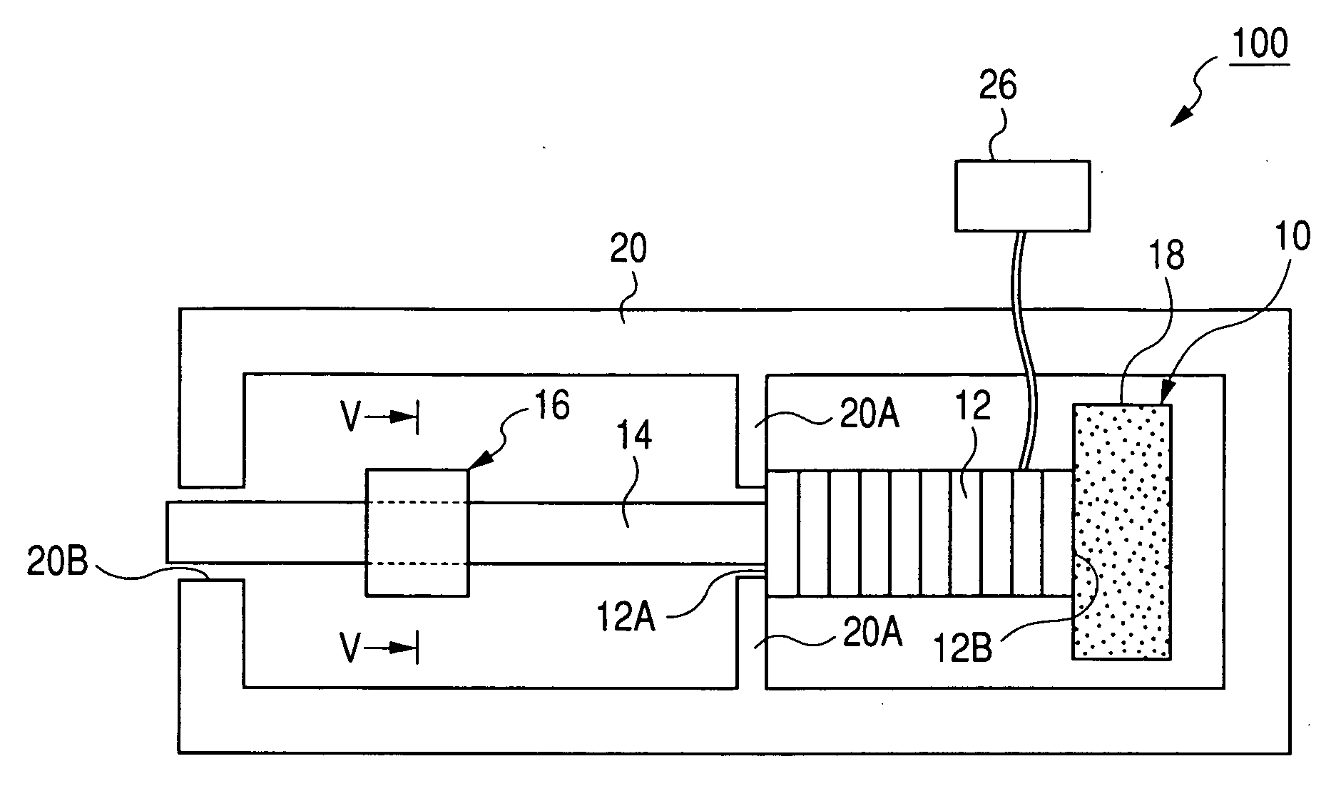
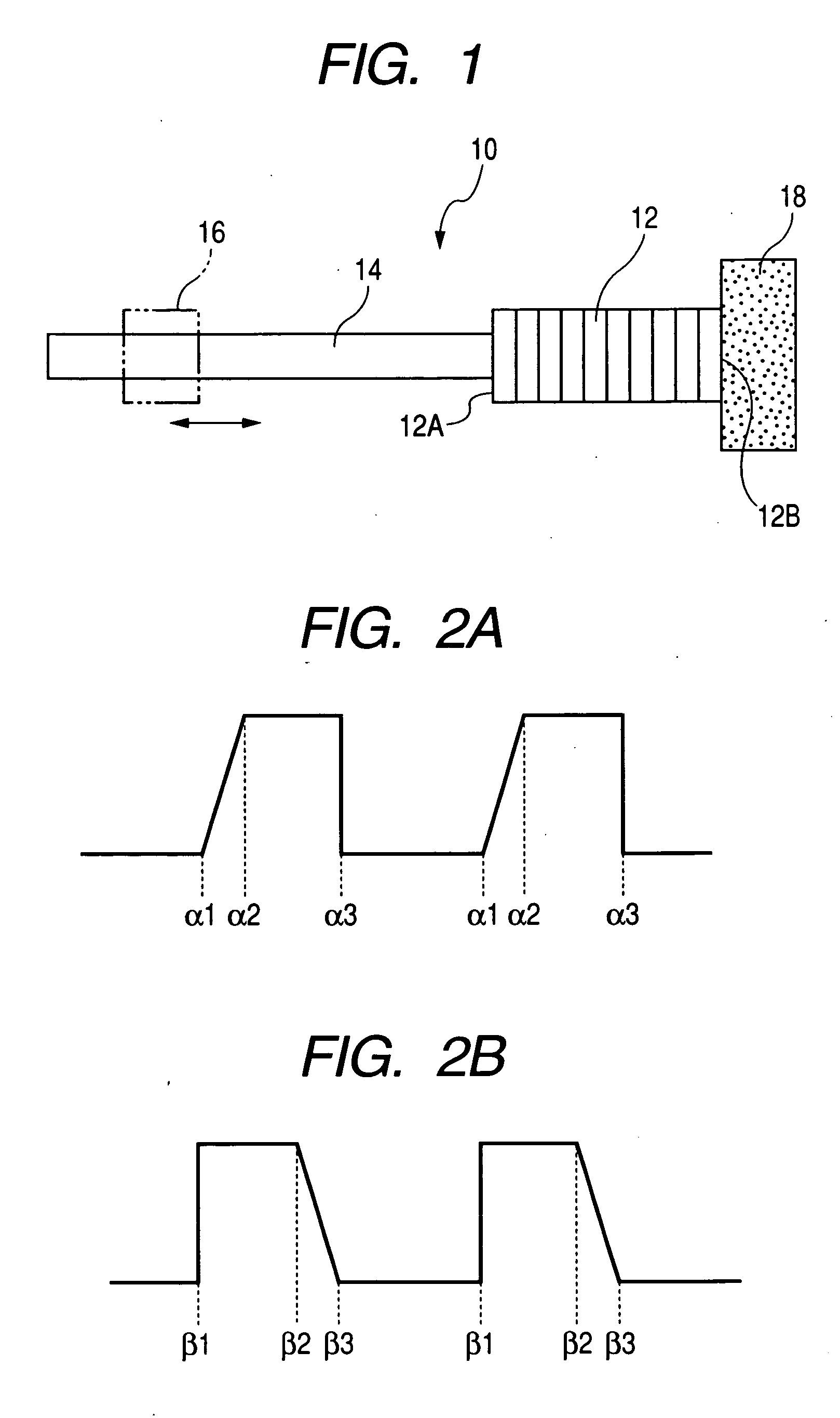
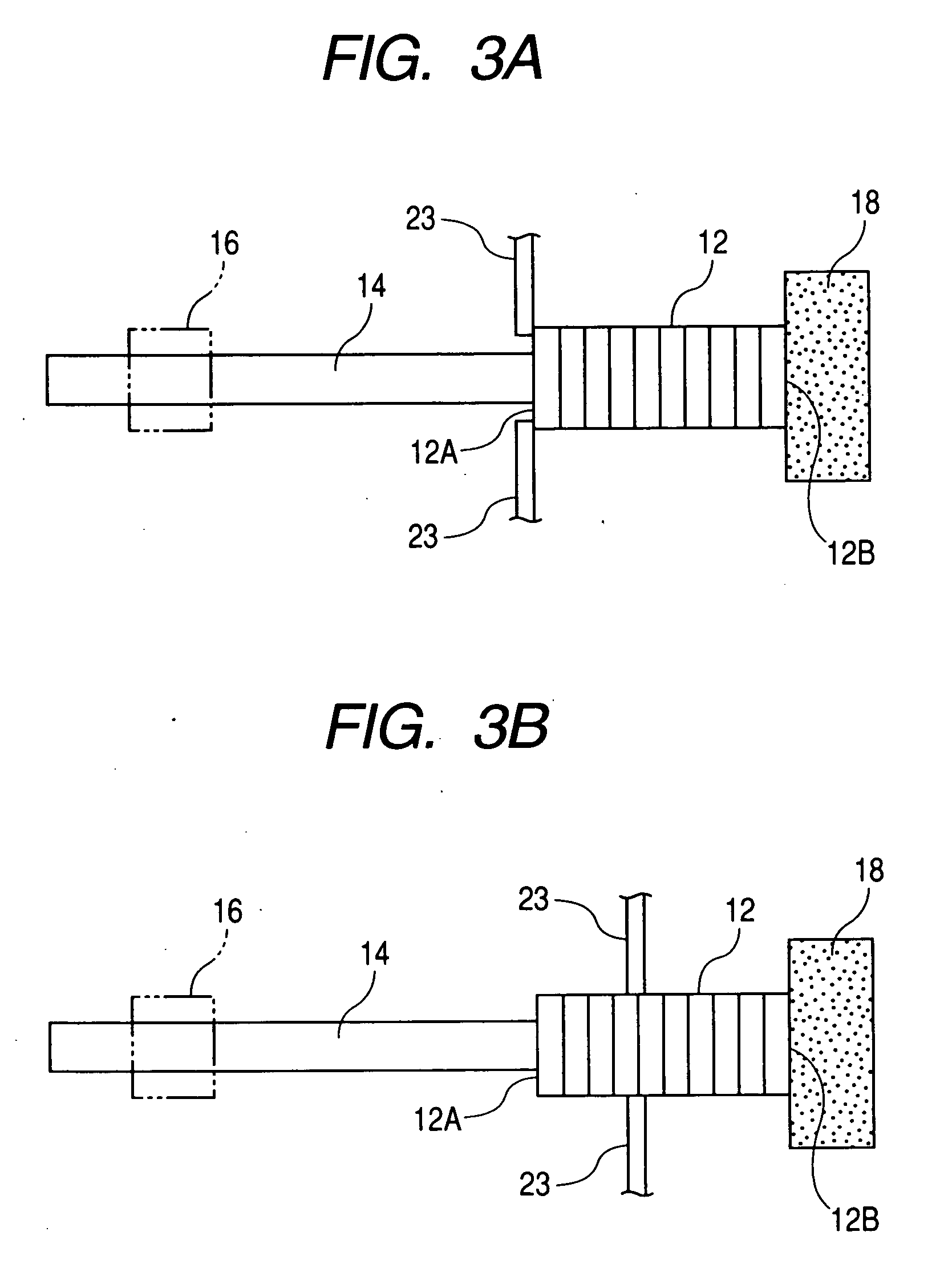
[0066]FIG. 1 is a plan view showing an actuator 10 of a driving mechanism 100 of a first embodiment in the present invention. As shown in FIG. 1, the actuator 10 is constituted by a piezoelectric element (corresponding to an electro-mechanical conversion element) 12, a driving member 14 and a weight member 18. The piezoelectric element 12 is laminated in the direction shown by the arrow and constituted so as to deform in a laminated direction (elongation and contraction) on application of voltage. Therefore, the piezoelectric element 12 is designed so that longer end surfaces 12A and 12B are displaced.
[0067] Of the end surfaces 12A and 12B of the piezoelectric element 12, to one end surface 12A is fastened a base end of the driving member 14. The driving member 14 is formed, for example, in a cylindrical shape, and its axis is arranged in the direction shown by the arrow (namely, in the elongating and contracting direction of the piezoelectric element). The driving member 14 is pref...
third embodiment
[0102] Next, an explanation will be made for a driving mechanism 300 of a third embodiment in the present invention with reference to FIG. 9.
[0103] As shown in FIG. 9, the driving mechanism 300 is different from the driving mechanism 200 in that a weight member 332 constituted by an elastic body such as rubber is adhered and fixed to the end surface 12B on the rear side of a piezoelectric element 12 and a surface opposite the piezoelectric element 12 in the weight member 332 is adhered and fixed to a body 20. The thus constituted mechanism is also able to provide effects and actions similar to those of the above embodiment.
fourth embodiment
[0104] Next, an explanation will be made for a driving mechanism 400 of a fourth embodiment in the present invention with reference to FIG. 10.
[0105] As shown in FIG. 10, the driving mechanism 400 is different from the driving mechanism 200 in that a weight member 418 made with a soft material is shaped into a thin plate form having a larger surface than the end surface 12B of a piezoelectric element 12, the piezoelectric element 12 is adhered and fixed at the center of the weight member 418, and both ends of the weight member 418 are adhered and fixed to a body 20. According to the thus constituted driving mechanism 400 of the present embodiment, since the end surface 12B at the rear end of the piezoelectric element 12 is supported to the body 20 by the thin-plate shaped weight member 418, the weight member 418 is deformed flexibly to cause displacement at the end surface 12B at the rear end of the piezoelectric element 12. Further, since the weight member 418 is small in Young's m...
PUM
 Abstract
Description
Claims
Application Information
 - R&D
- Intellectual Property
- Life Sciences
- Materials
- Tech Scout
- Unparalleled Data Quality
- Higher Quality Content
- 60% Fewer Hallucinations
Browse by: Latest US Patents, China's latest patents, Technical Efficacy Thesaurus, Application Domain, Technology Topic, Popular Technical Reports.
© 2025 PatSnap. All rights reserved.Legal|Privacy policy|Modern Slavery Act Transparency Statement|Sitemap|About US| Contact US: help@patsnap.com


