Transmission line transformer

a transformer and transmission line technology, applied in the field of transformers, can solve the problems of reducing the efficiency of power amplifiers in regions where relatively low output power is outputted, the inability to guarantee the dynamic range of the source voltage only by controlling the voltage vdd, and the inability of power amplifiers to reduce detrimental interference, etc., to achieve the effect of improving efficiency

Active Publication Date: 2006-10-19
KOREA ADVANCED INST OF SCI & TECH
View PDF3 Cites 13 Cited by
  • Summary
  • Abstract
  • Description
  • Claims
  • Application Information

AI Technical Summary

Benefits of technology

[0034] The transmission line transformer according to the present invention can improve efficiency and a dynamic range of a power amplifier as its primary side is separated to form a plurality of primary transmission

Problems solved by technology

However, the conventional power amplifier has disadvantages in that its sufficient dynamic range cannot be guaranteed by only control of the source voltage VDD.
However, the wireless communication system requires a relatively wide dynamic range.
However, since load impedance Rload of the conventional power amplifier is set to a proper value to meet with the maximum value of the output power Pout, the power amplifier decreases its efficiency in a region where a relatively low output power is outputted.
However, the method disclosed in the above-mentioned journal has disadvantages

Method used


Image

  • Transmission line transformer
  • Transmission line transformer
  • Transmission line transformer

Examples


Embodiment Construction

[0048] While the invention has been shown and described with respect to the preferred embodiments, it will be understood by those skilled in the art that various changes and modifications may be made without departing from the scope and spirit of the invention. Thus, the scope of the invention should not be limited by the embodiments of the present invention.

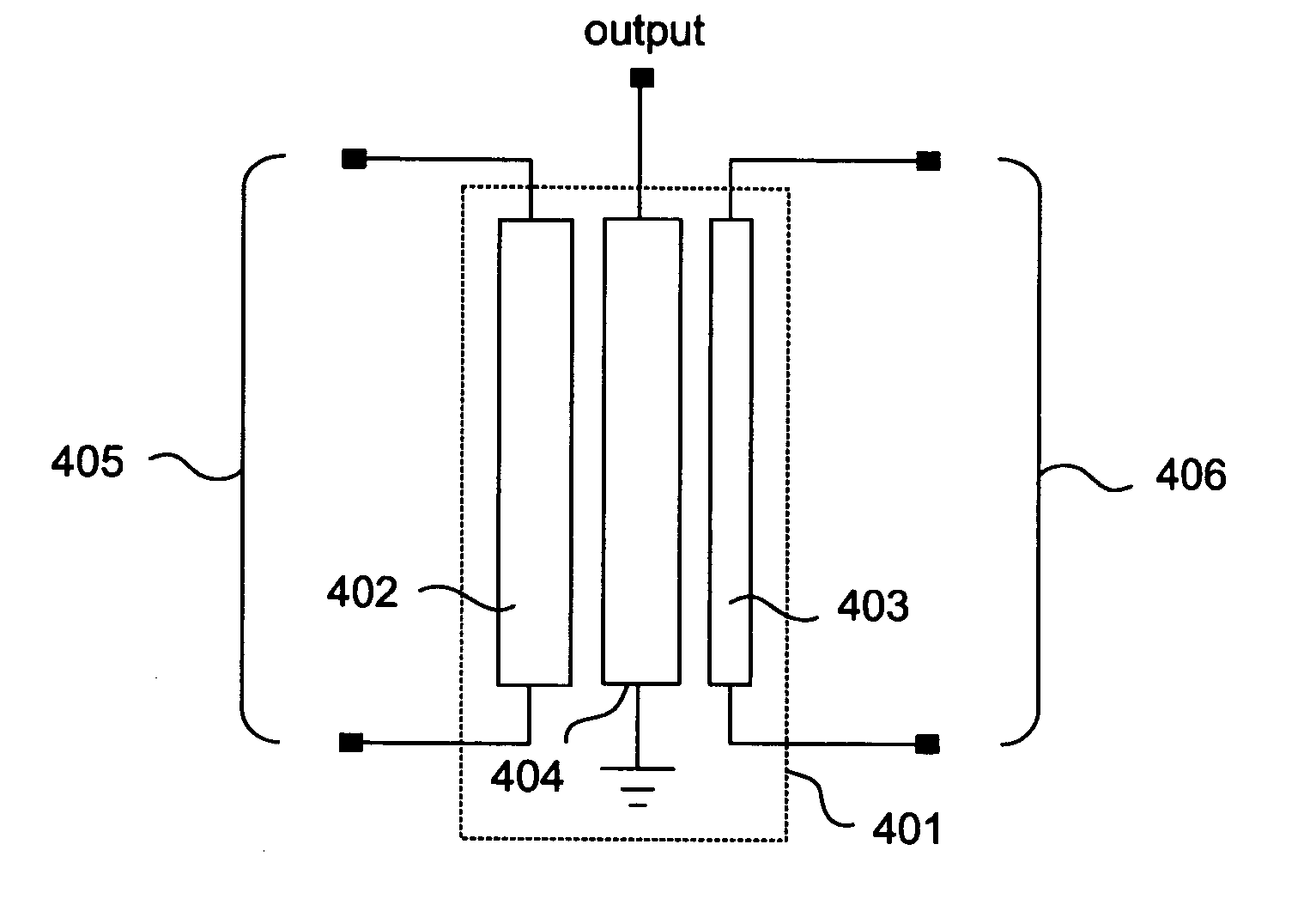
[0049]FIG. 4A is a circuit diagram of a transmission line transformer according to the present invention, and FIG. 4B is a view illustrating a structure of the transmission line transformer according to the present invention.

[0050] As shown in FIG. 4A, the transmission line transformer includes a secondary transmission line 404, and a plurality of primary transmission lines 402 and 403 which are correspondingly aligned at both sides of the secondary transmission line 404, respectively, in which the primary transmission lines have parasitic components which are different from each other.

[0051] Here, the plurality of primary tr...


PUM


Abstract

A transmission line transformer is disclosed. The transformer improves efficiency and a dynamic range of a power amplifier. The transformer is formed to have a plurality of load impedances as the primary side of the transmission line transformer is separated to form a plurality of primary transmission lines with parasitic components which are different from each other. The transformer is used as an impedance matching circuit of the power amplifier requiring a plurality of load impedances.

Description

BACKGROUND OF THE INVENTION [0001] 1. Field of the Invention [0002] The present invention relates to a transformer, and more particularly to a transmission line transformer which is capable of improving efficiency and a dynamic range of a power amplifier, and which is formed to have a plurality of load impedances as the primary side of the transmission line transformer is separated to form a plurality of primary transmission lines with parasitic components which are different from each other, in which the transmission line transformer is used as an impedance matching circuit of the power amplifier requiring a plurality of load impedances. [0003] 2. Description of the Related Art [0004] Generally, a power amplifier requiring a plurality of load impedances is usually used in a wireless communication system. [0005]FIG. 1 is a schematic block diagram of a power amplifier of a general art, or a power amplifier with a polar structure which is a type of wireless communication system. [0006...

Claims


Application Information

Patent Timeline
IPC IPC(8): H01P5/04H01P1/06H03H2/00
CPCH01P5/02H03F1/08H01P5/04H03F3/20
Inventor PARK, CHANGKUNKIM, YOUNSUKHONG, SONGCHEOL
Owner KOREA ADVANCED INST OF SCI & TECH
Why Eureka
Try Eureka