Coordinate input apparatus, control method thereof, and program

Active Publication Date: 2006-10-19
CANON KK
View PDF5 Cites 63 Cited by
  • Summary
  • Abstract
  • Description
  • Claims
  • Application Information

AI Technical Summary

Benefits of technology

[0105] In a preferred embodiment, the light shielding detection window is a portion in a range defined by setting an upper end to a higher one of an upper end of a light projecting window serving as a portion effectively contributing to light projection in the sensor means and an upper end of a light receiving window serving as a portion effectively contributing to light reception and a lower end to a higher one of a lower end of the light projecting window and a lower end of the light receiving window.

Problems solved by technology

However, the shadow intensity (the rate of light intensity decrease by light shielding) does not always take the same value for the sensors because of the positional relationship between the sensors and the retroreflecting member and the positional relationship between the light projecting units and the light receiving units in each sensor.
When the shadow that must be detected cannot be detected by one of the sensors, the input coordinates cannot be detected accurately.
The influence of this problem is especially serious when a plurality of inputs are done simultaneously by a plurality of pointers.
For example, if a shadow which should be detectable by a given sensor cannot be detected, the sensor erroneously senses that the shadow overlaps another shadow.

Method used


Image

  • Coordinate input apparatus, control method thereof, and program
  • Coordinate input apparatus, control method thereof, and program
  • Coordinate input apparatus, control method thereof, and program

Examples


first embodiment

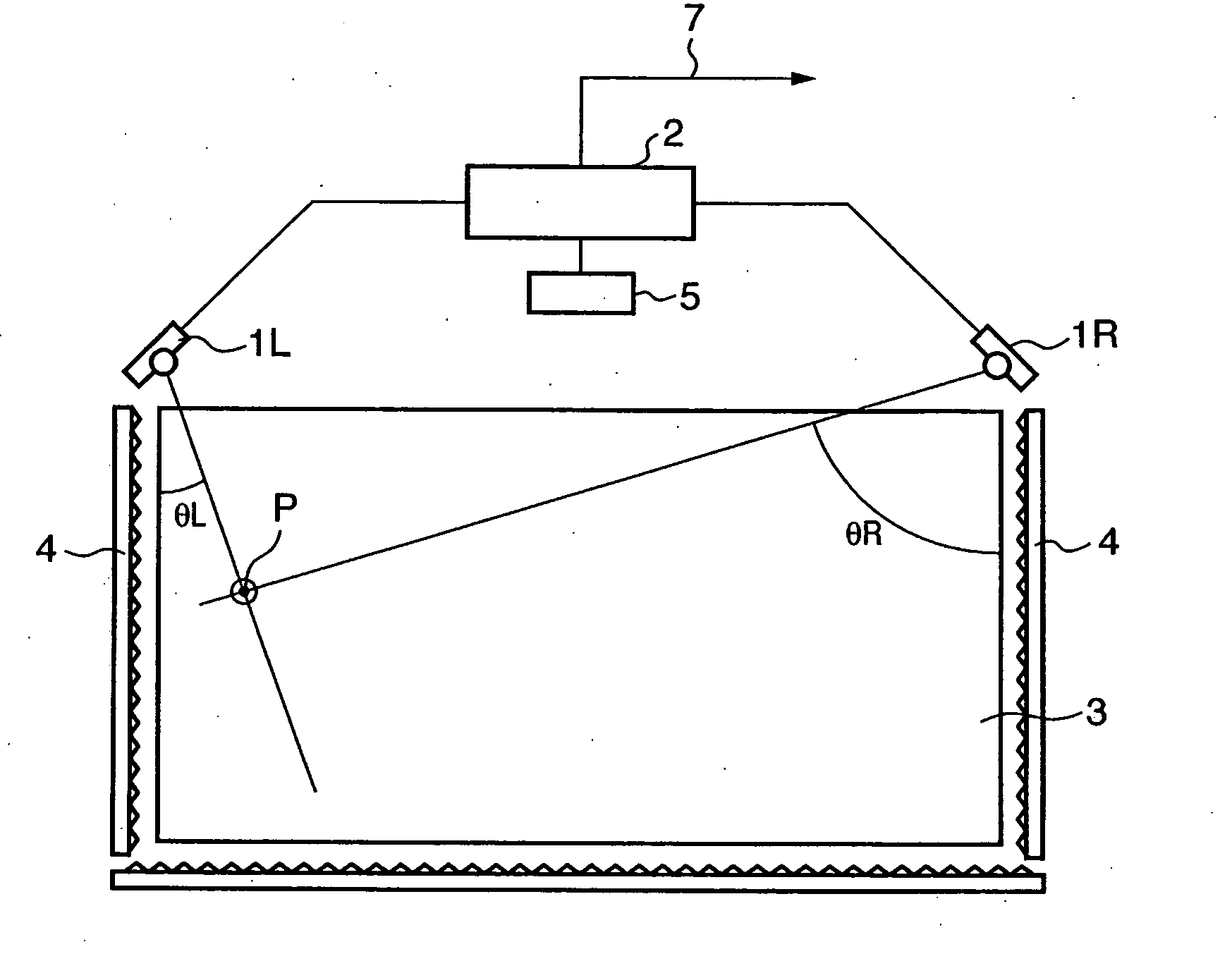
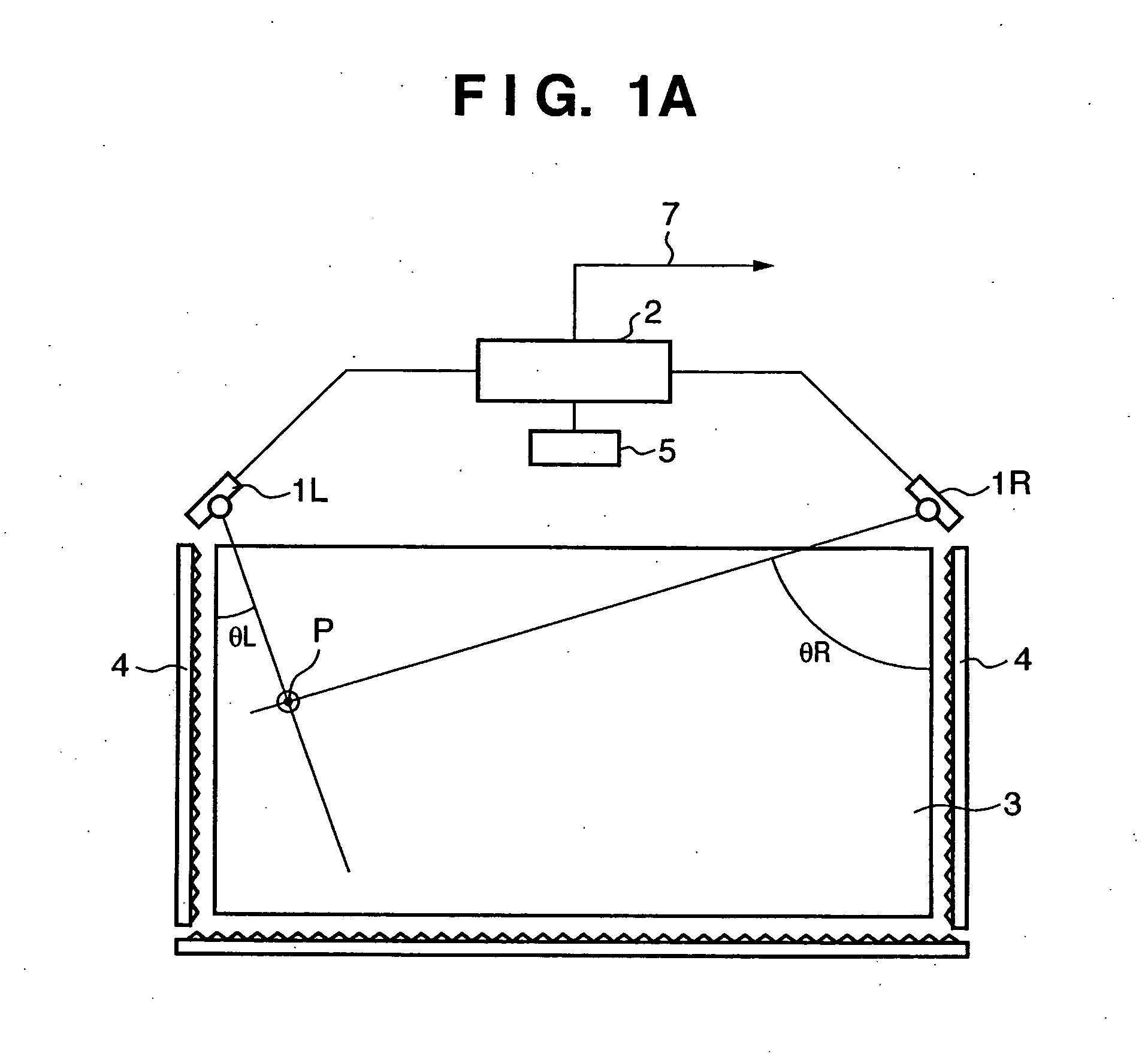
[0205]FIG. 1A is a view showing the arrangement of a coordinate input apparatus of light shielding scheme according to the first embodiment of the present invention.

[0206] Referring to FIG. 1A, sensor units 1L and 1R have light projecting units and light receiving units. In the first embodiment, the sensor units 1L and 1R are arranged parallel to the X-axis of a coordinate input effective region 3 serving as a coordinate input surface and symmetrically about the Y-axis while being spaced apart by a predetermined distance, as shown in FIG. 1A. The sensor units 1L and 1R are connected to a control / arithmetic unit 2. Each of the sensor units 1L and 1R receives a control signal from the control / arithmetic unit 2 and transmits a detected signal to the control / arithmetic unit 2.

[0207] A retroreflecting member 4 has a retroreflecting surface to reflect incident light in the direction of arrival. The retroreflecting member 4 is arranged on three outer sides of the coordinate input effecti...

second embodiment

[0301]FIG. 13 is a view showing the arrangement of a coordinate input apparatus of light shielding scheme according to the second embodiment of the present invention.

[0302] The basic arrangement of the coordinate input apparatus shown in FIG. 13 is the same as that of the coordinate input apparatus shown in FIG. 1A. In the first embodiment, the detailed arrangement of the sensor units 1L and 1R have not been described particularly. This will be described in the second embodiment.

[0303] Each of the sensor units 1L and 1R of the first embodiment incorporates one set of a light projecting unit and a light receiving unit. In the second embodiment shown in FIG. 13, each of sensor units 1L and 1R includes two sets of light projecting units and light receiving units. That is, the first embodiment employs a single-lens structure in which one optical unit is incorporated in one sensor unit. However, the second embodiment employs a multiple-lens (twin-lens) structure in which two optical un...

third embodiment

[0407] In the third embodiment, an arrangement will be described in which a sensor unit 1C is newly added to the arrangement of the first embodiment shown in FIG. 1A, as shown in FIG. 30.

[0408]FIG. 30 shows multiple point input in points P12 and P21.

[0409] In this case, as shown in FIG. 31A, a sensor unit 1L detects shadows at positions θL1 and θL2. As shown in FIG. 31B, a sensor unit 1R detects shadows at positions θR1 and θR2. As shown in FIG. 31C, the sensor unit 1C detects shadows at positions θC1 and θC4. On the basis of the three sets of angle data, four coordinate candidate points P11, P12, P21, and P22 are calculated. When truth determination is executed for these coordinate candidate points by a certain means, for example, P11 and P22 are determined as real images, and P12 and P21 are determined as virtual images. Hence, the coordinate input points can be decided.

[0410] The sensor unit 1C shown in FIG. 30 has almost the same arrangement as the sensor unit 1L or 1R except...


PUM


Abstract

The point state of a pointer in a coordinate input region is determined on the basis of the number and intensities of shadows which are present in light intensity distributions obtained from a plurality of sensors in accordance with pointing by the pointer.

Description

FIELD OF THE INVENTION [0001] The present invention relates to a coordinate input apparatus for detecting a point position on a coordinate input region, a control method thereof, and a program. BACKGROUND OF THE INVENTION [0002] There exist coordinate input apparatuses which are used to input coordinates to a coordinate input surface by using a pointer (e.g., a dedicated input pen or finger) to control a connected computer or write characters and graphics. [0003] Conventionally, as coordinate input apparatuses of this type, touch panels of various schemes have been proposed or become commercially available. These apparatuses are widely used because a terminal such as a personal computer can easily be operated on the screen without using any special tool. [0004] There are various coordinate input schemes using, e.g., a resistive film or an ultrasonic wave. A scheme using light is disclosed in, e.g., U.S. Pat. No. 4,507,557. In U.S. Pat. No. 4,507,557, a retroreflecting sheet is provi...

Claims


Application Information

Patent Timeline
IPC IPC(8): G01B11/14
CPCG02B5/124G06F3/0421G06F3/0416G06F3/04166
Inventor KOBAYASHI, KIWAMU
Owner CANON KK
Why Eureka
Try Eureka