
Image Forming Apparatus and Image Forming Method

a technology of image forming apparatus and forming method, which is applied in the direction of electrographic process apparatus, instruments, optics, etc., can solve the problems of insufficient density of an image to be formed and insufficient and achieve the effect of high efficiency of the developing process

Inactive Publication Date: 2009-12-03
SEIKO EPSON CORP
View PDF3 Cites 6 Cited by
  • Summary
  • Abstract
  • Description
  • Claims
  • Application Information

AI Technical Summary

Benefits of technology

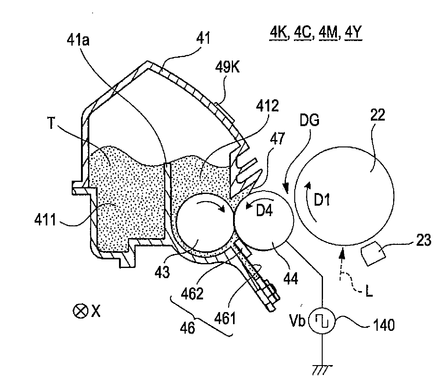
[0007]An advantage of some aspects of the invention is that it provides an image forming apparatus and an image forming method, which use a toner carrying roller having the surface on which regular concave-convexes are disposed, capable of having the toner carried in the toner carrying roller to effectively contribute to a developing process so as to acquire sufficient image density.
[0012]As described above, according to the above-described aspect, by having he reciprocating movement of the toner according to the developing bias and the movement of the surface of the toner carrying roller to be synchronized with each other, the toner carried in the concave portion can be effectively lifted off. Accordingly, more pieces of toner can contribute to the developing process. As a result, the efficiency of the developing process is increased, and thereby an image can be formed with sufficient image density.
[0015]In addition, in an image forming apparatus in which the image carrier and the toner carrying roller are disposed to face each other with a predetermined gap interposed therebetween, the advantages of the aspects of the invention are prominent. In such an apparatus, the developing process is performed by reciprocating flight of the toner in the gap between the image carrier and the toner carrying roller. The toner flying from the concave portion induces flight of the toner in another concave portion, and accordingly, a high efficiency of the developing process is acquired.
[0016]In addition, the above-described image forming apparatus may be configured to include further a regulating unit that is brought into contact with the surface of the toner carrying roller on an upstream side relative to the opposing position in the rotation direction of the toner carrying roller and regulates attachment of the toner to top faces of the plurality of convex portions. Under such a configuration, carrying the toner is almost limited to the concave portions, and thus, it is very important to increase the efficiency of the developing process. By applying the invention to the apparatus having the above-described configuration, sufficient image density can be acquired by increasing the efficiency of the developing process.
[0017]In addition, the above-described image forming apparatus may further include a sealing member that prevents leakage of the toner from a housing is interposed in a gap between the surface of the toner carrying roller and the housing on a downstream side relative to the opposing position in the direction of rotation of the toner carrying roller, wherein a shaft of the toner carrying roller is attached to the housing, which stores the toner therein, so as to be rotatable. Under such a configuration, toner attached to the convex portion may be pressed between the convex portion and the sealing member so as to be fixed to the sealing member or the toner carrying roller. However, according to an embodiment of the invention, the toner carried in the concave portion is returned to the concave portion. Accordingly, toner that is attached to the convex portion on the downstream side relative to the opposing position of the image carrier and the toner carrying roller is decreased. As a result, an advantage that such fixation cannot easily occur can be acquired.
[0020]According to a third aspect of the invention, there is provided an image forming method. The image forming method includes: forming an electrostatic latent image on a surface of an image carrier; and developing the electrostatic latent image with toner by applying an AC voltage as a developing bias to a toner carrying roller by disposing the toner carrying roller, which rotates in a predetermined direction with charged toner carried on a surface thereof, so as to face the image carrier. In addition, periodical concavo-convexes that are formed of a plurality of convex portions arranged at a constant pitch in a circumferential direction and concave portions that surround the plurality of convex portions are formed on the surface of the toner carrying roller. When the arrangement pitch is denoted by P, the frequency of the developing bias is denoted by F, and the moving speed of the surface of the toner carrying roller for the circumferential direction is denoted by V, a quotient acquired from dividing V by F is a value acquired from multiplying P by a natural number or an approximately natural number. According to the above-described image forming method, same as the above-described image forming apparatus, an image having sufficient image density can be formed with a high efficiency of the developing process.

Problems solved by technology

Even when a height difference of the concave-convex is configured to be large for supplementing a decrease in the amount of transport of the toner accompanied with the small effective surface area of the toner carrying roller, toner that is carried in a deep portion of the concave portion cannot easily contribute to a developing process, and thereby the efficiency of the developing process is not sufficient.
Accordingly, there is a case where the density of an image to be formed is insufficient.

Method used


Image

  • Image Forming Apparatus and Image Forming Method
  • Image Forming Apparatus and Image Forming Method
  • Image Forming Apparatus and Image Forming Method

Examples


Embodiment Construction

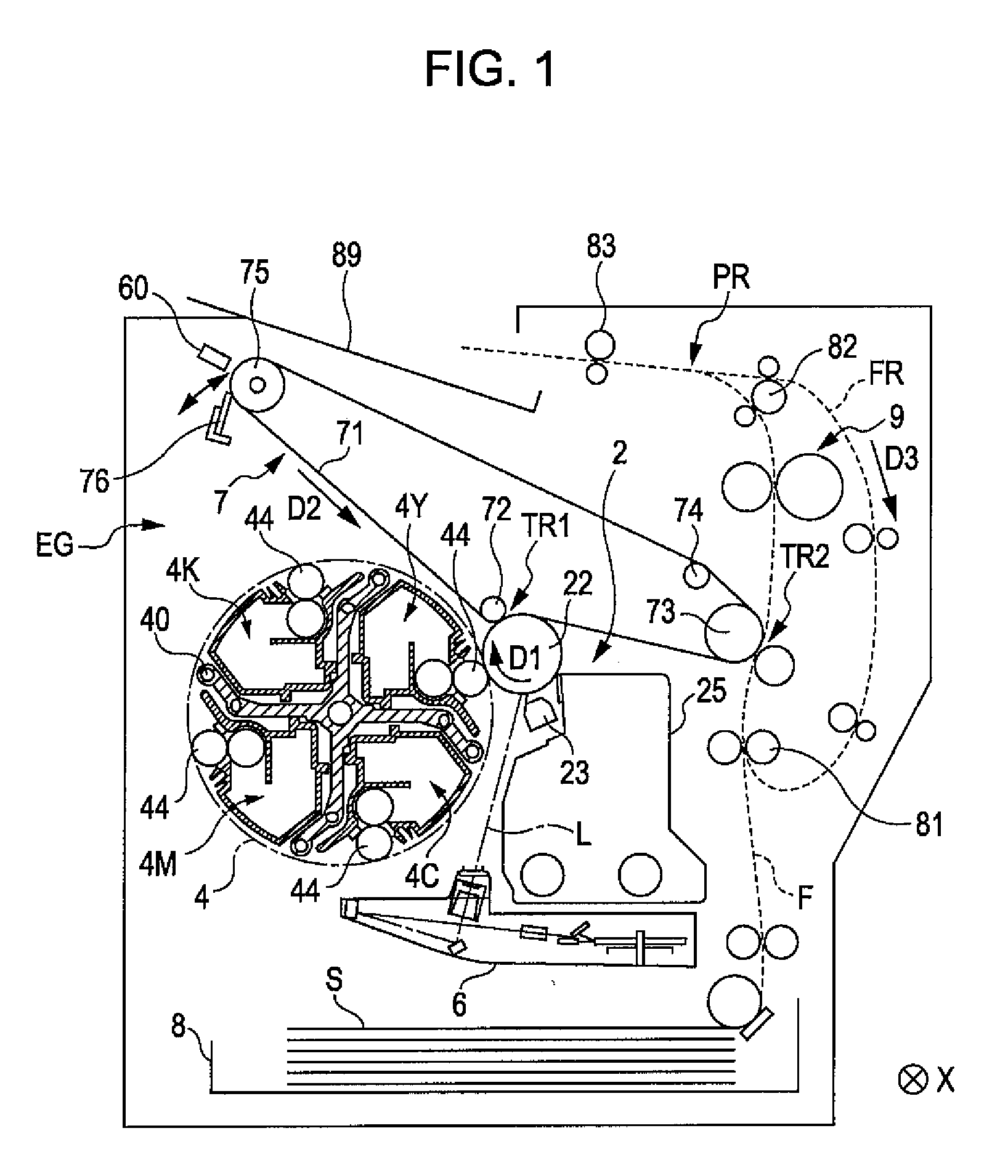
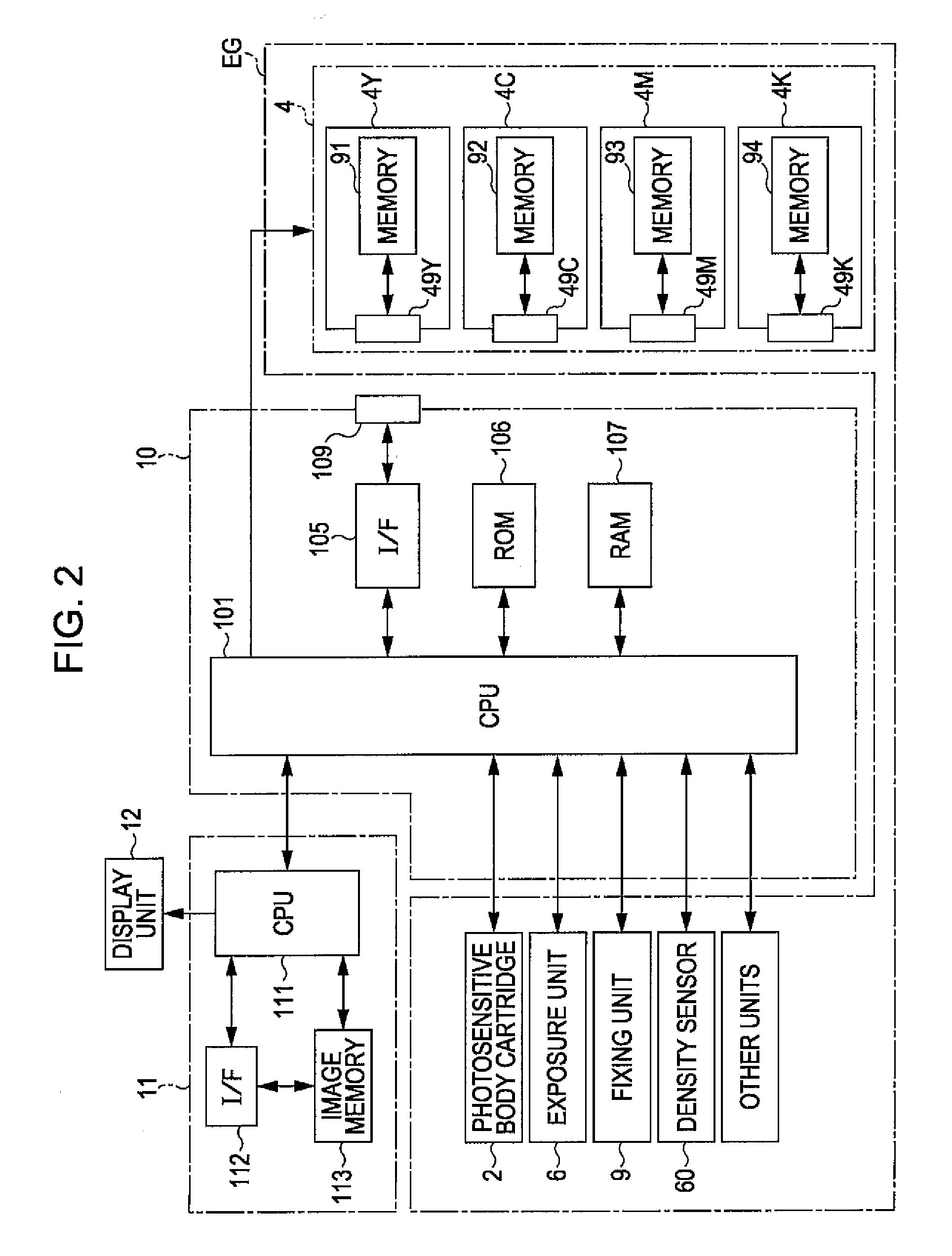
[0030]FIG. 1 is a diagram showing an image forming apparatus according to an embodiment of the invention. In addition, FIG. 2 is a block diagram showing the electrical configuration of the image forming apparatus shown in FIG. 1. This apparatus is an image forming apparatus that forms a full color image by superimposing toner (developers) of four colors including a yellow (Y) color, a cyan (C) color, a magenta (M) color, and a black (K) color or forms a monochrome image by using toner of the black (K) color only. When an image signal is supplied to a main controller 11 of this image forming apparatus from an external apparatus such as a host computer, a CPU 101 that is disposed in an engine controller 10 controls sections of an engine unit EG in accordance with a direction transmitted from this main controller 11 so as to perform a predetermined image forming operation and whereby forming an image corresponding to the image signal on a sheet S.

[0031]In this engine unit EG, a photose...


PUM


Abstract

An image forming apparatus includes an image carrier that carries an electrostatic latent image on a surface thereof, a toner carrying roller that is disposed to face the image carrier and rotates in a predetermined rotation direction with charged toner carried on a surface thereof so as to transport the toner in an opposing position for facing the image carrier, and a bias applying unit that develops the electrostatic latent image with the toner by applying an AC voltage as a developing bias to the toner carrying roller. In addition, periodical concavo-convexes that are formed of a plurality of convex portions arranged at a constant pitch in a circumferential direction and concave portions that surround the plurality of convex portions are formed on the surface of the toner carrying roller. When the arrangement pitch is denoted by P, the frequency of the developing bias is denoted by F, and the moving speed of the surface of the toner carrying roller for the circumferential direction is denoted by V, a quotient acquired from dividing V by F is a value acquired from multiplying P by a natural number or an approximately natural number.

Description

BACKGROUND[0001]1. Technical Field[0002]The present invention relates to an image forming apparatus and an image forming method that develops an electrostatic latent image with toner by using a toner carrying roller having a surface on which periodic concave-convexes are disposed.[0003]2. Related Art[0004]Recently, developing devices for developing an electrostatic latent image carried on an image carrier with toner and image forming apparatuses having the developing devices in which a toner carrying roller that is formed in an approximate cylinder shape and carries toner on the surface is disposed to face an image carrier have been widely used. The applicant of this application, in order to enhance the characteristics of toner that is carried on the surface of the toner carrying roller, has disclosed an image forming apparatus, which employs a toner carrying roller in which convex portions that are regularly disposed on the surface of the roller formed in a cylinder shape and conca...

Claims


Application Information

Patent Timeline
IPC IPC(8): G03G15/08
CPCG03G15/0818
Inventor ARUGA, TOMOHIROMAEDA, MASAHIRO
Owner SEIKO EPSON CORP
Learn More