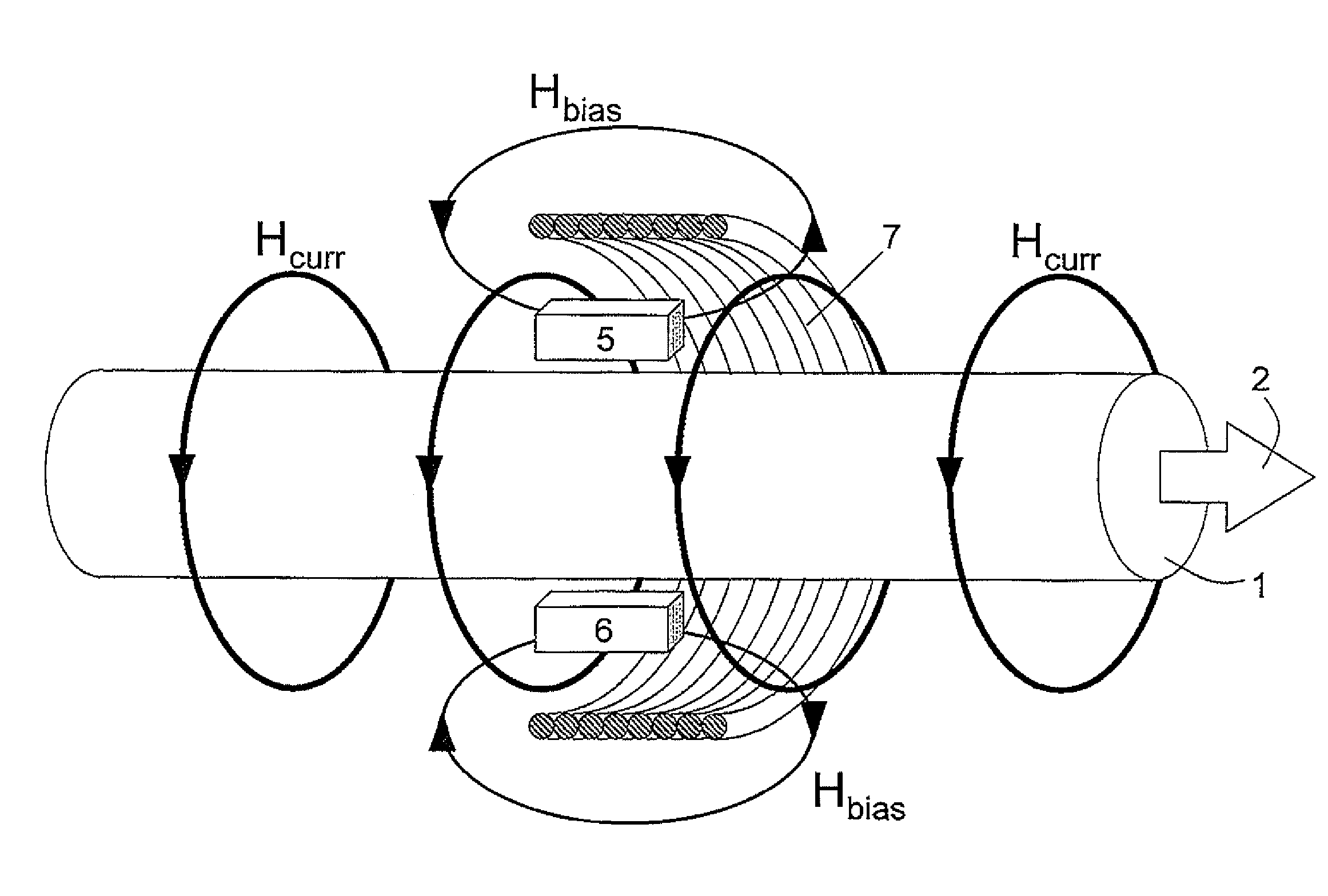
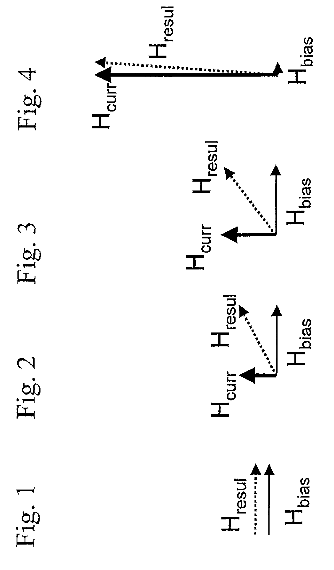
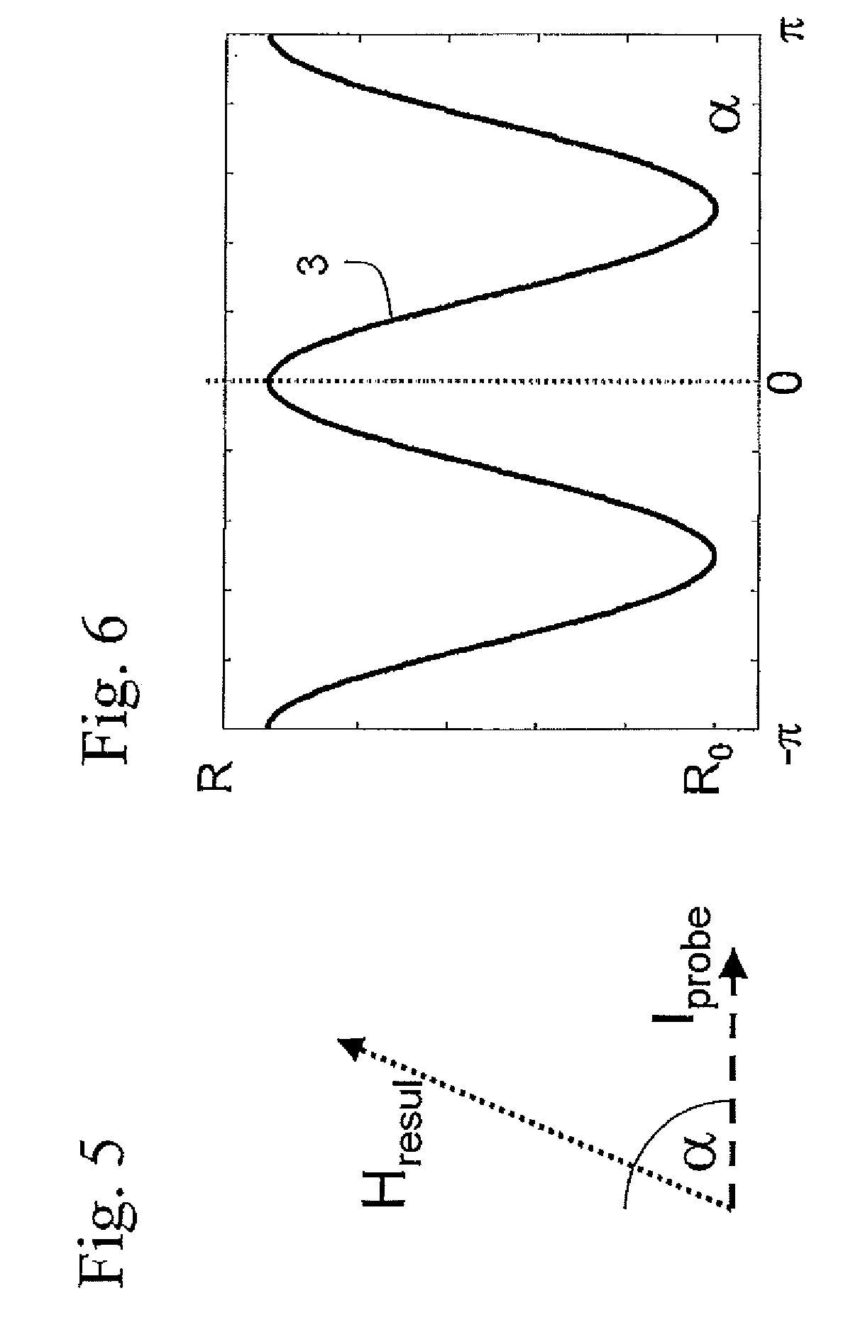
[0011]One of the key elements of the sensor unit according to the invention is the fact that it has been found that a magnetoresistive sensor can continuously be operated in the saturation regime by applying a corresponding bias field, which essentially eliminates offset and hysteresis problems associated with conventional operation of such sensors. It is furthermore astonishingly efficiently possible to use the angular dependency of the measurement signal in the sensor produced by the vector sum Hresul of the field of the current to be measured Hcurr and the bias field Hbias. Typically to this end the direction of the bias magnetic field Hbias provided by the auxiliary coil is oriented at an angle of more than 45°, preferably at an angle of more than 60°, most preferably at an angle of in the range of 80-100° with respect to the direction of the magnetic field Hcurr produced by the current in the conductor to provide a high angular sensitivity of the measurement signal. Magnetoresistive sensors have two stable magnetizations. One of these is addressed by the bias field. However, if the tilt angle is larger than a few degrees in the wrong direction, then the magnetic field corresponding to the peak current will flip the magnetization of the material and thus invert the signal. When using two sensors in the device one of the sensors will, if the bias field is tilted, automatically have a tilt into the wrong direction and the other will not. This is leading to a signal which can not be interpreted unambiguously any more. Therefore preferably the above angle is in the range of 90°+ / −2°.
[0012]So a new measurement device based on magnetoresistive sensors is proposed in order to overcome the difficulties for the detection of small current signals on top or after large current peaks. The new method directly measures the magnetic field generated by the main current. It allows the detection of frequencies up to 1 MHz without showing any significant distortions of the signal due to the large currents, and especially without creating an offset during or after the measurements.
[0016]According to a further preferred embodiment, at least one pair of magnetoresistive sensors (typically located opposite with respect to the main axis of the conductor), preferably at least two or three pairs of magnetoresistive sensors are distributed symmetrically around the circumference of the conductor. The provision of at least a pair of sensors allows to compensate for external field contributions quite efficiently. Indeed typically external field contributions are essentially homogeneous on the dimensional scale of the sensor, which therefore in view of the rotationally symmetric setup in particular in case of an auxiliary coil coaxial with the conductor allows a cancelling of the external field contributions when summing up the signals of the pairs of sensors. Preferably the sensors are located as close as possible to the conductor where the field of the conductor is strongest, so normally at a distance in the range of 0-10 mm, preferably 0-5 mm, as concerns their sensing region, from the outer surface of the conductor. The minimal distance is given by the required dielectric isolation between the conductor and the sensors, and is often at least 2-3 mm.
[0018]More specifically, according to a further preferred embodiment, such a sensor unit may comprise an isolating inner supporting element, preferably of essentially cylindrical shape, enclosing the conductor (non-conducting mount). Such an isolating inner supporting element on its outer surface or at least partially embedded therein (for example in corresponding cavities or recesses) carrying at least one magnetoresistive sensor. Particularly low interference of the connections to the sensors can be achieved if in this context preferably the electrical connections to the sensor are when coming from the sensor first axially (for example over a distance of at least 5 mm) and subsequently radially guided away from the sensor (for example in correspondingly provided channels or recesses in the isolating inner supporting element). Further preferably an outer supporting element is provided. Also this outer supporting element can be of essentially cylindrical shape and is radially enclosing the inner element and the sensors located thereon / therein (essentially sandwiching the sensors between the inner and the outer supporting element). It is preferred if on the outer element's outer circumference or at least partially embedded into its outer circumference it carries the auxiliary coil, preferably as a multiturn winding around and coaxial with the axis of the conductor at the position where the sensors are located. Typically the inner supporting element and / or the outer supporting element are made of fluorinated materials, for example selected from PTFE and chemical modifications / blends thereof. Since in particular in case of AC measurements there can be heavy mechanical stress on the sensor unit, it is preferred if the winding of the auxiliary coil is firmly fixed to the sensor unit, which, according to a further preferred embodiment, it is possible if the multiturn winding is resin cast onto or into the outer supporting element. To this end for example of the outer supporting element can be provided with a corresponding outer circumferential recess into which the multiturn winding can be laid and subsequently fixed by filling the recess with a resin or a corresponding fixation material.
[0024]According to a further preferred embodiment of the sensor unit according to the present invention, it further comprises an electronics unit for controlling the magnetoresistive sensors and for feeding the at least one auxiliary coil and for amplifying and / or evaluating the signals of the magnetoresistive sensors. It should be noted that the available sensitivity of the sensor unit is very high and therefore care has to be taken that no “magnetic noise or interference signal” is produced by the lines leading to or from the sensors and / or by the electronics unit. One means to keep interfering signals as low as possible in the above-mentioned way of first axially and subsequently radially guiding away the lines to and from the sensors. Another additional possibility is to avoid the noise induced by transformers for powering the electronics unit. To this end one may either use a completely or heavily shielded transformer or, as preferred, it is possible to use an electronics unit which is essentially exclusively powered by the use of at least one battery unit (e.g. rechargeable). Furthermore it is advisable to make sure that the electronics unit is built of components of low magnetic and / or electric field noise producing components.
[0027]Such a use of a sensor further preferably takes place with an additional coil for the generation of a time dependent subtraction magnetic field aiming to keep the resulting field within the sensitivity range of the sensor allowing for a precise measurement of the difference between the compensation field and the resulting one. The compensation field can be generated e.g. by using a feedback mechanism, a low-frequency current measurement, or a predefined waveform. Applications of this use are in particular the detection of small variations / harmonics on a 50 Hz signal by compensating for a perfect sinusoidal signal of the correct amplitude (which might be adjusted with a feed back or low frequency measurement), precise measurement of deviation from any expected current waveform, measurement of any current by compensating as well as possible using a feed back, where the feed back signal is a measure for the current.