Eureka AIR delivers breakthrough ideas for toughest innovation challenges, trusted by R&D personnel around the world.

Method of converting image data, image data conversion apparatus and program

Inactive Publication Date: 2006-10-19
DAINIPPON SCREEN MTG CO LTD
View PDF6 Cites 13 Cited by
  • Summary
  • Abstract
  • Description
  • Claims
  • Application Information

AI Technical Summary

Benefits of technology

[0015] According to the present invention, when the first image data represented by colors including a spot color is converted into the second image data represented only by process colors, the second image data obtained by the conversion reflects both a change in gradation of the process colors and a change in gradation of the spot color without the saturation of the color densities even if overprinting occurs in the first image data. Thus, when the generation of the proof image data from the raster data involves pseudocolorization, the present invention achieves the generation of the image data having a color representation more appropriate than that obtained by a conventional method.
[0016] It is therefore an object of the present invention to provide an apparatus for and method of converting first printing image data having a color representation including a spot color into second printing image data having a color representation not including the spot color, the apparatus and method being capable of appropriately providing color density values representing overprinted colors in the second printing image data.

Problems solved by technology

However, many output apparatuses of such a type are not capable of producing output including the spot color, but are capable of producing only output using the process plates.
Thus, such output apparatuses, when used for the proof output of printed materials including the spot color, cannot produce the output for a spot color image and finally cannot produce the output which meets the purpose of checking the color representation and the like.
Therefore, this method is not capable of representation of gradation which reflects the overprint.
This presents the problem that the overprint cannot be said to be faithfully represented.
This technique, however, is similar to the MAX combination method in that the overprint cannot be said to be faithfully represented because the remaining density value is neglected.

Method used


Image

  • Method of converting image data, image data conversion apparatus and program
  • Method of converting image data, image data conversion apparatus and program
  • Method of converting image data, image data conversion apparatus and program

Examples


first preferred embodiment

[0033]

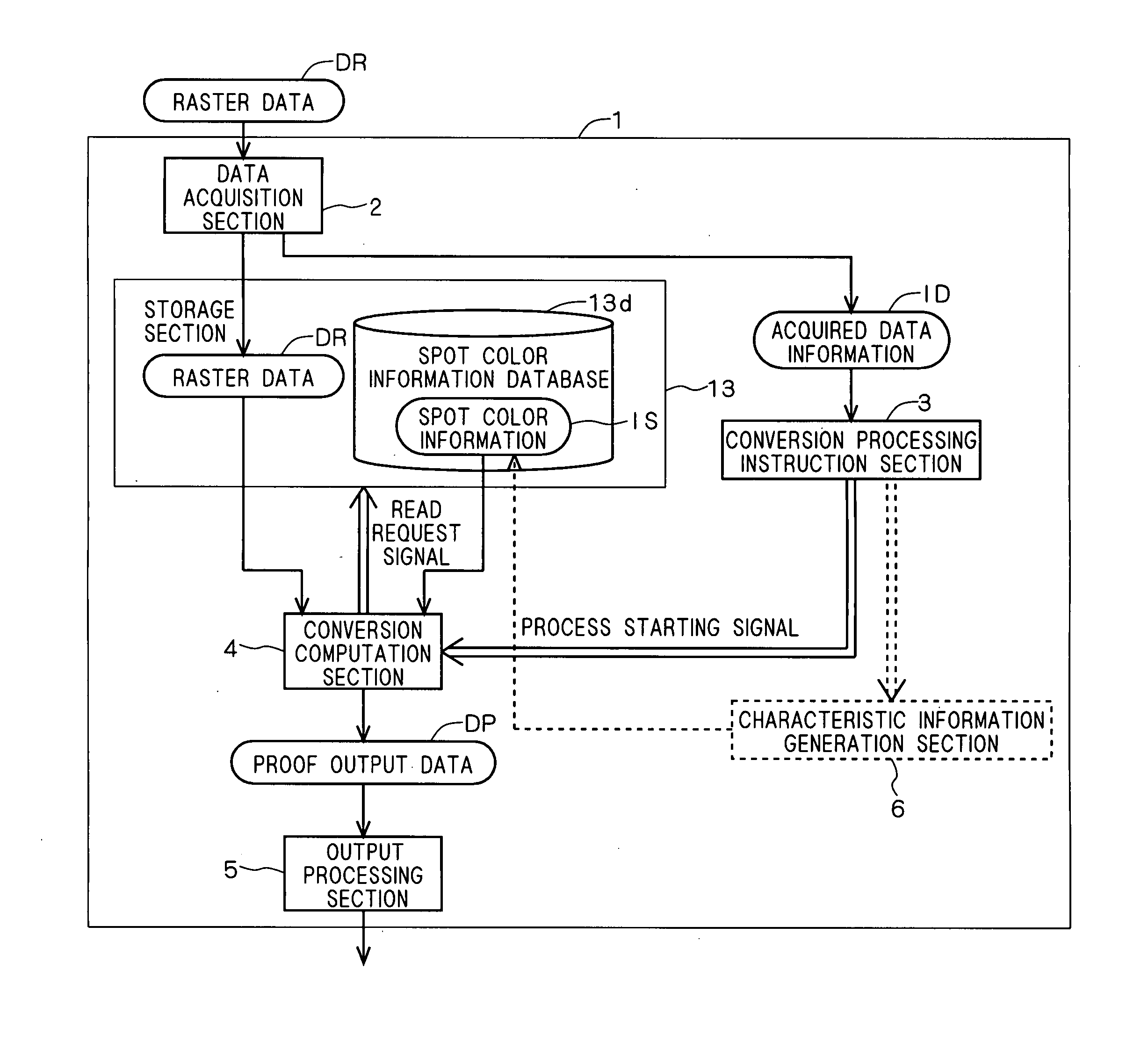
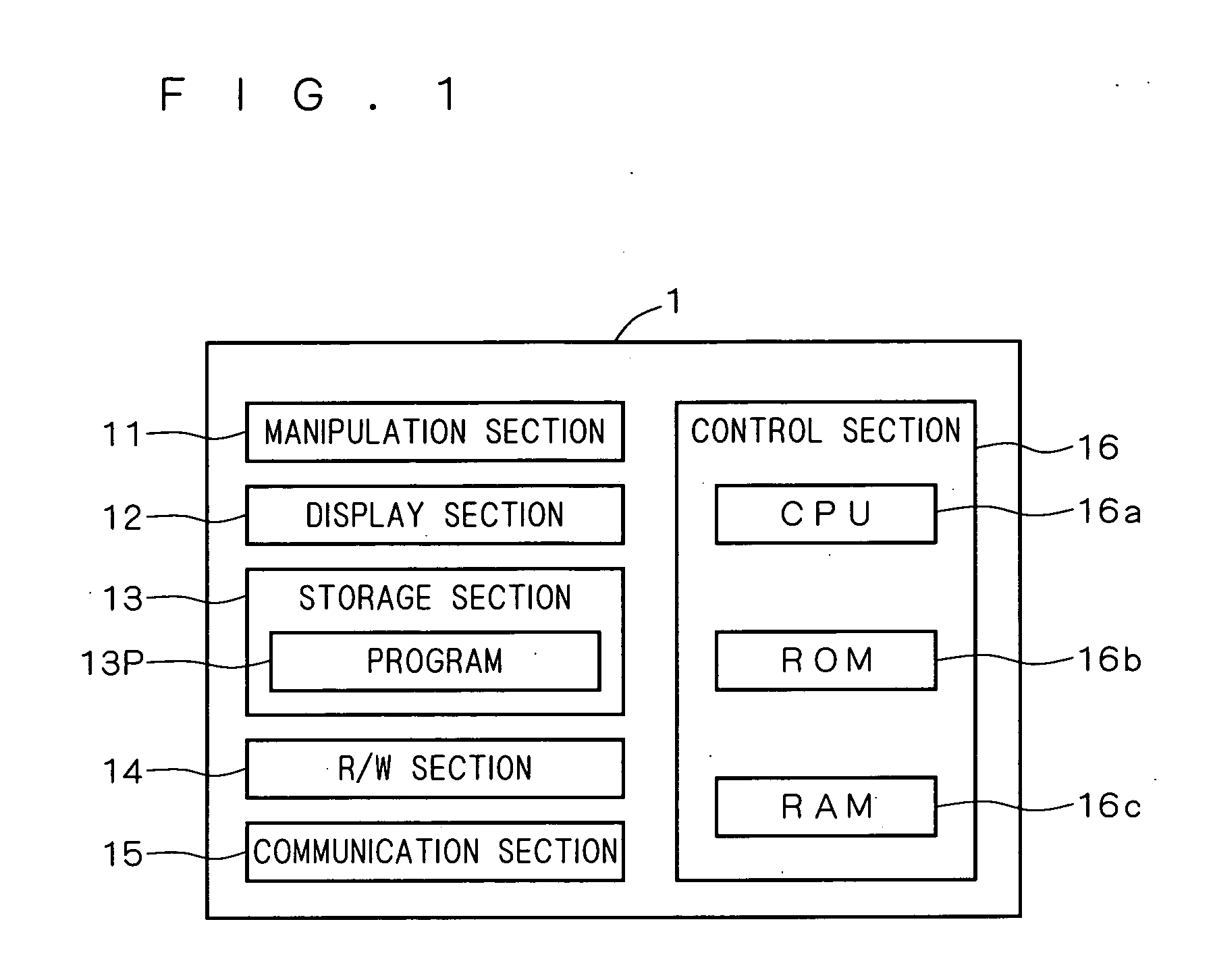
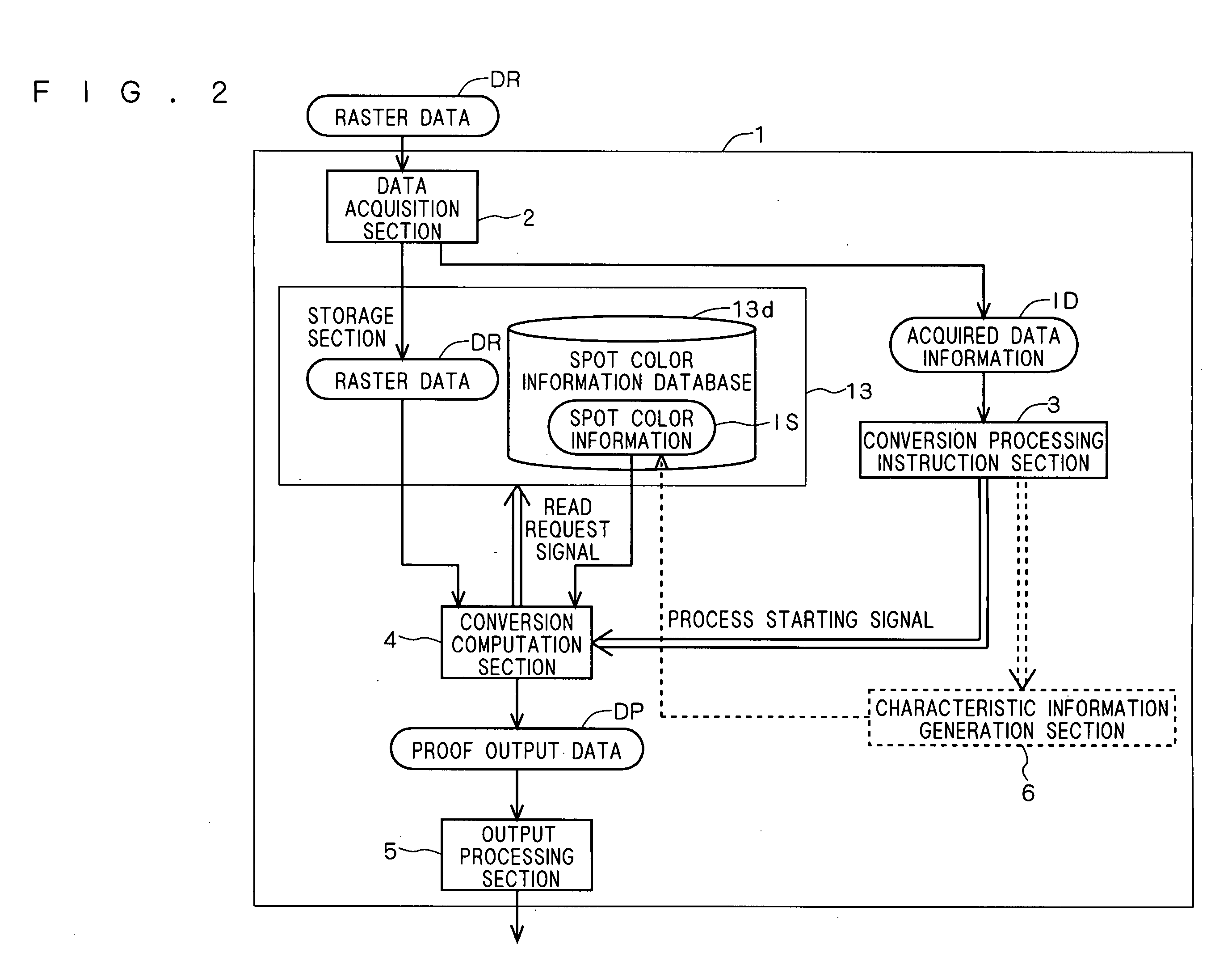
[0034]FIG. 1 is a schematic diagram showing the construction of an image data conversion apparatus 1 according to a first preferred embodiment of the present invention. The image data conversion apparatus 1 is an apparatus implemented, for example, by a computer. The image data conversion apparatus 1 executes a predetermined program 13p thereby to convert bitmap-format printing image data (e.g., raster data obtained by a rasterization process) color-designated on a pixel-by-pixel basis for a plurality of color components including a spot color into bitmap-format image data which does not include the spot color.

[0035] The image data conversion apparatus 1 can be used in any stage of printing workflow if there arises a need for the above-mentioned image data conversion. It is not necessary that a single computer is configured to have only the function of the image data conversion apparatus 1, but the single computer may be configured to implement a different function by the exe...

second preferred embodiment

[0079] The first preferred embodiment illustrates the conversion computation for the pseudocolorization of a single spot color in the case of the overprinting using a spot color plate for the single spot color and a process plate. A second preferred embodiment of the present invention will illustrate a conversion computation for the pseudocolorization of two different spot colors in the case of the overprinting of the two different spot colors. There arises a need for such a conversion computation when producing proof output having an overprint using only the spot colors by means of a proof output apparatus capable of representing only the process colors. In such a case, a conversion computation expression for the color conversion process can be derived by discussion similar to that of the first preferred embodiment. The operations of the sections of the image data conversion apparatus 1 in the second preferred embodiment are basically similar to those in the first preferred embodim...


PUM


Abstract

A conversion computation section acquires the original color density value of a single process color in a given image region and the original color density value of a spot color from raster data, and acquires a pseudocolor conversion rate for conversion from the spot color to the process color from spot color information. Then, the conversion computation section calculates a proof color density value Hi of each process color on a pixel-by-pixel basis in each image region by using a conversion computation expressed by Hi=Pi+s·Gi−Pi·s·Gi where Pi (i=C, M, Y or K) is the original color density value of the single process color, s is the original color density value of the spot color, and Gi is the pseudocolor conversion rate for conversion from the spot color to the process color. The proof color density value reflects a change in gradation of the process color and a change in gradation of the spot color without the saturation of the color density.

Description

BACKGROUND OF THE INVENTION [0001] 1. Field of the Invention [0002] The present invention relates to a technique for converting a color representation used in spot color printing into a color representation which does not include the spot color. More particularly, the invention relates to a technique for appropriately determining color density values when colors are overprinted. [0003] 2. Description of the Background Art [0004] A large number of color printed materials are created by the use of plates (or process plates) prepared for respective basic colors known as process colors (typically the following four colors: C (cyan); M (magenta); Y (yellow); and K (black)) (or by the use of data about color density values corresponding to the plates for the respective color components in plateless printing). When there is a need for printing using a color which cannot be sufficiently represented by the process plates or a color which is not permitted to vary, it is customary to prepare a...

Claims


Application Information

Patent Timeline
IPC IPC(8): H04N1/60
CPCH04N1/60H04N1/46
Inventor FURUKAWA, ITARU
Owner DAINIPPON SCREEN MTG CO LTD
Why Eureka
Eureka Blog
Learn More