Methods and apparatus for reducing data capture and storage requirements for call and transaction related message monitoring and fraud detection

Inactive Publication Date: 2006-10-19
VERIZON PATENT & LICENSING INC
View PDF10 Cites 6 Cited by
  • Summary
  • Abstract
  • Description
  • Claims
  • Application Information

AI Technical Summary

Benefits of technology

[0028] The method of the present invention involves the passing of information, e.g., in one or more messages, from the monitoring equipment in the source network to that in the destination network. This information may be and often is passed separate and apart from the signaling used to set up and tear down calls themselves, and requires a connection that allows direct communication between source and destination monitoring equipment. However, it has the advantage, compared to the known system, in which signaling for all calls to the destination network are monitored and logged for further analysis, of reducing the amount of data storage capacity and subsequent processing resources required to detect call fraud or other anomalies relating to calls placed from a source network to a destination network area of interest. Thus, the methods of the present invention are well suited for real-time or near real-time fraud detection and / or for cases where storage capacity may be an issue. The methods and apparatus of the present invention may offer a cost effective and hardware efficient solution to the issue of fraud monitoring and / or trouble detection. Thus, the methods of the present invention are well suited for areas where the volume of network traffic does not justify the cost of deploying equipment capable of monitoring, logging and processing of information corresponding to all calls. The message passing / call monitoring methods of the present invention can be used as a supplement to a partially deployed exhaustive call monitoring system and / or as a cost effective / hardware efficient alternative to such a system.
[0039] Various origination and destination monitoring points, such as end-office switches, Signaling Transfer Points (STPs), etc. may be selected for the placement of monitoring equipment in accordance with the invention. In some embodiments, the monitoring equipment is advantageously placed on elements near an inter-network boundary, e.g., interfacing to an Inter-Exchange Carrier (IXC), rather than on each switch in a given area, thus limiting the total number of monitoring points and the amount of monitoring equipment used.

Problems solved by technology

This may present logistical difficulties with regard to both the storage required to hold the saved messages, as well as the additional processing required to analyze them.
This results in information being logged for many calls where no corresponding source / destination information will be available, since the calls may originate or terminate at a different carrier's network or an unmonitored portion of the monitoring carrier's own network.
Thus, there will be some delay between when an inappropriate modification occurs and when it is actually detected.
Such alterations may make the call appear to the destination network 110 as an intra-state interLATA, or local call, resulting in improper billing and a loss of revenue to destination network 110 due to fraud on the part of the intermediate network 108.
Such alterations may make the call appear to the destination network 110 as a local call, or an interstate call, resulting in improper billing and a loss of revenue to destination network 110 due to fraud on the part of the intermediate network 108.

Method used


Image

  • Methods and apparatus for reducing data capture and storage requirements for call and transaction related message monitoring and fraud detection
  • Methods and apparatus for reducing data capture and storage requirements for call and transaction related message monitoring and fraud detection
  • Methods and apparatus for reducing data capture and storage requirements for call and transaction related message monitoring and fraud detection

Examples


Embodiment Construction

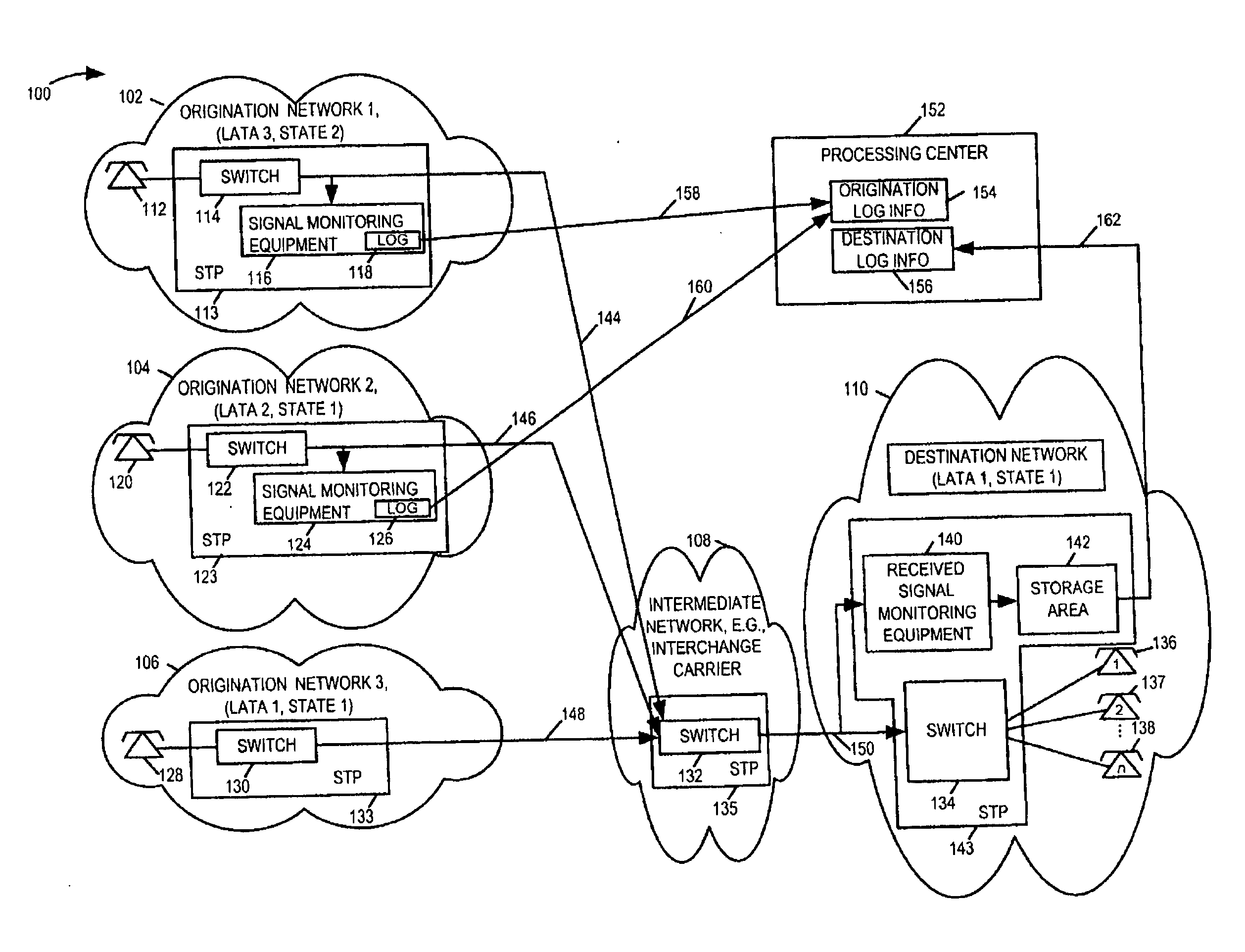
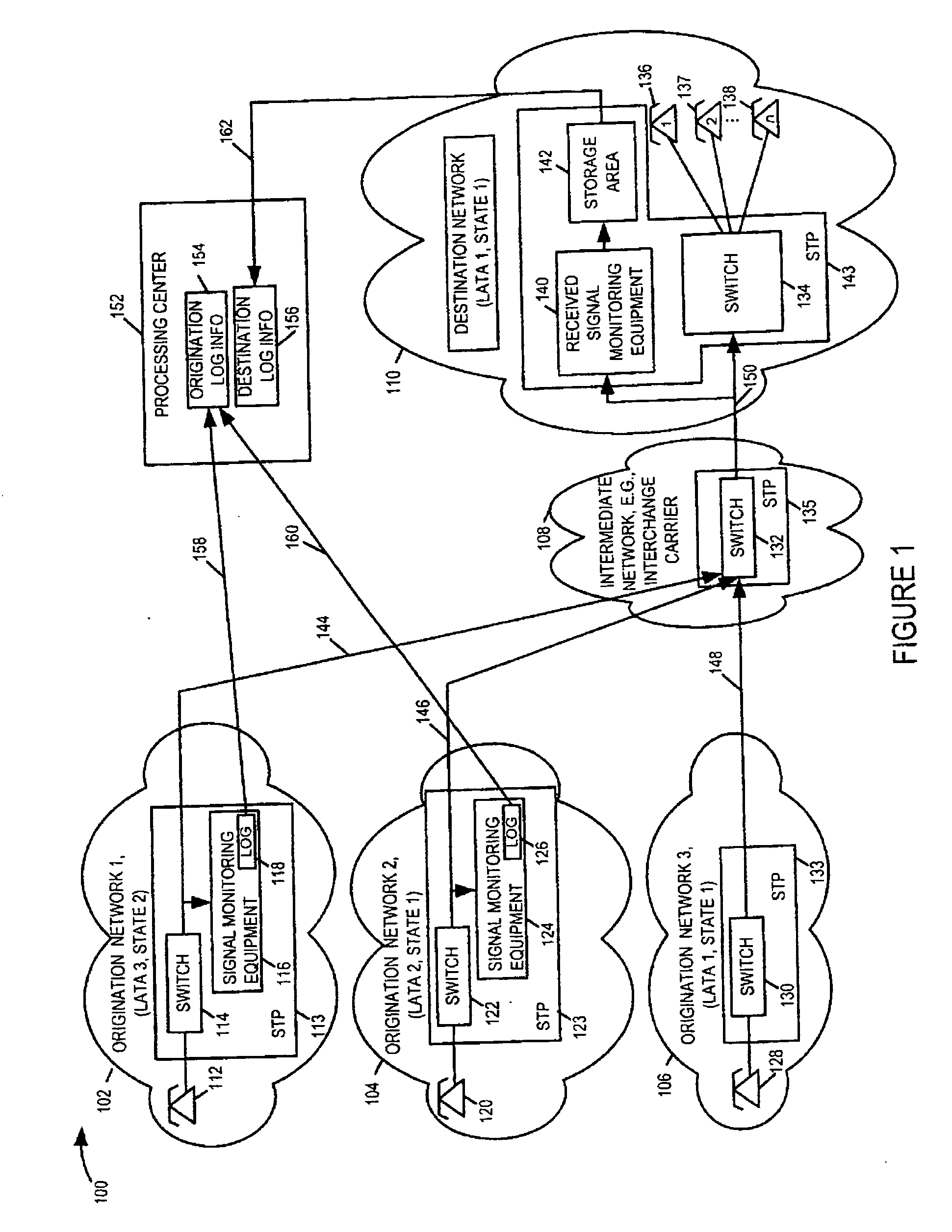
[0042]FIG. 3 is a drawing of an exemplary communications system 300 for call monitoring using apparatus and methods in accordance with the present invention. System 300 includes a first origination network 302, a second origination network 304, a third origination network 306, an intermediate network 308, and a destination network 310. Subscribers in the first, second, and third origination networks 302, 304, 306 can place calls to subscribers in destination network 310 via intermediate network 308 which couples the first, second, and third networks 302, 304, 306 to destination network 310. In FIG. 3 each of the different LATAs corresponds to a different local area.

[0043] The destination network 310 is located in LATA 1 of state 1. Origination network 3, 306 is also located in LATA 1 of state 1. Calls from origination network 3, 306 directed to destination network 310 are considered local calls. Origination network 2, 304 is located in LATA 2 of state 1. Calls from origination netw...


PUM


Abstract

Systems for monitoring, storage, and analysis of information in signaling messages, communicated from originating networks to a destination network through one or more intermediate networks are described. Correlation and comparison between signaling messages of interest sent from an origination network to signaling messages received by the destination network allows for the detection of inconsistent information, e.g., information fields in a communicated message that have been altered, either intentionally or unintentionally, by an intermediate carrier. The introduction of an additional communications path over which notification messages are forwarded from signaling monitoring equipment in the origination network to signaling monitoring equipment in the destination network allows for a significant reduction in the memory storage requirements at the destination network and in the amount of processing required to match, compare, and evaluate signaling messages. In addition, the reduction in stored messages and processing time allows the monitoring system to operate in near-real time allowing for fraud detection while a call is still in progress.

Description

FIELD OF THE INVENTION [0001] The present invention relates generally to the field of telephone communications and, more particularly, to the field of monitoring, capturing, correlating, and comparing signaling messages exchanged between indirectly connected network segments. BACKGROUND [0002] In telephony today, the signaling messages and information used to: (i) establish and tear down a call, and (ii) to conduct transactions, often pass through one or more intermediary networks, e.g., interchange carriers, hub providers, on the way from their originator to their intended destination. Carriers, e.g., local carriers, have a number of reasons to implement call and transaction monitoring systems that collect, correlate, and compare the information that leaves an originating network with the information that enters a terminating network. These reasons include: maintaining and monitoring service assurance, troubleshooting problems, and detecting fraudulent manipulation of signaling inf...

Claims


Application Information

Patent Timeline
IPC IPC(8): H04M3/22
CPCH04L63/14H04Q2213/13383H04M7/06H04M7/12H04M15/41H04M15/58H04M15/70H04M15/73H04M2203/6027H04M2215/0164H04M2215/0188H04M2215/70H04M2215/7072H04Q2213/1307H04Q2213/13091H04Q2213/13103H04Q2213/1313H04Q2213/13176H04Q2213/13213H04Q2213/13216H04Q2213/13339H04Q2213/13352H04M3/2281
Inventor DOSKOW, ARTHURHETZ, HARRY A.HASENAUER, GEORGE ROBERTGEBHARDT, ERIK GEORGEVECCHIOLI, JOSEPH
Owner VERIZON PATENT & LICENSING INC
Why Eureka
Try Eureka