
Reflex hammer

a technology of reflex hammer and hammer head, which is applied in the field of reflex hammer, can solve the problems of increasing the chance of the patient inadvertently leaving, reducing the practical value of the device, and only marginally improving the functionality of the design, so as to improve the desirability and corresponding marketability of the object, increase the tension, and increase the functionality of the reflex hammer

Inactive Publication Date: 2006-10-19
SUN COAST MERCHANDISE
View PDF12 Cites 4 Cited by
  • Summary
  • Abstract
  • Description
  • Claims
  • Application Information

AI Technical Summary

Benefits of technology

[0010] An object of the present invention is to provide a reflex hammer which will become a highly desirable and indeed, an indispensable item for the medical practitioner. To do so, the present invention is configured as a foldable device which the practitioner may easily and comfortably fit in any pocket.
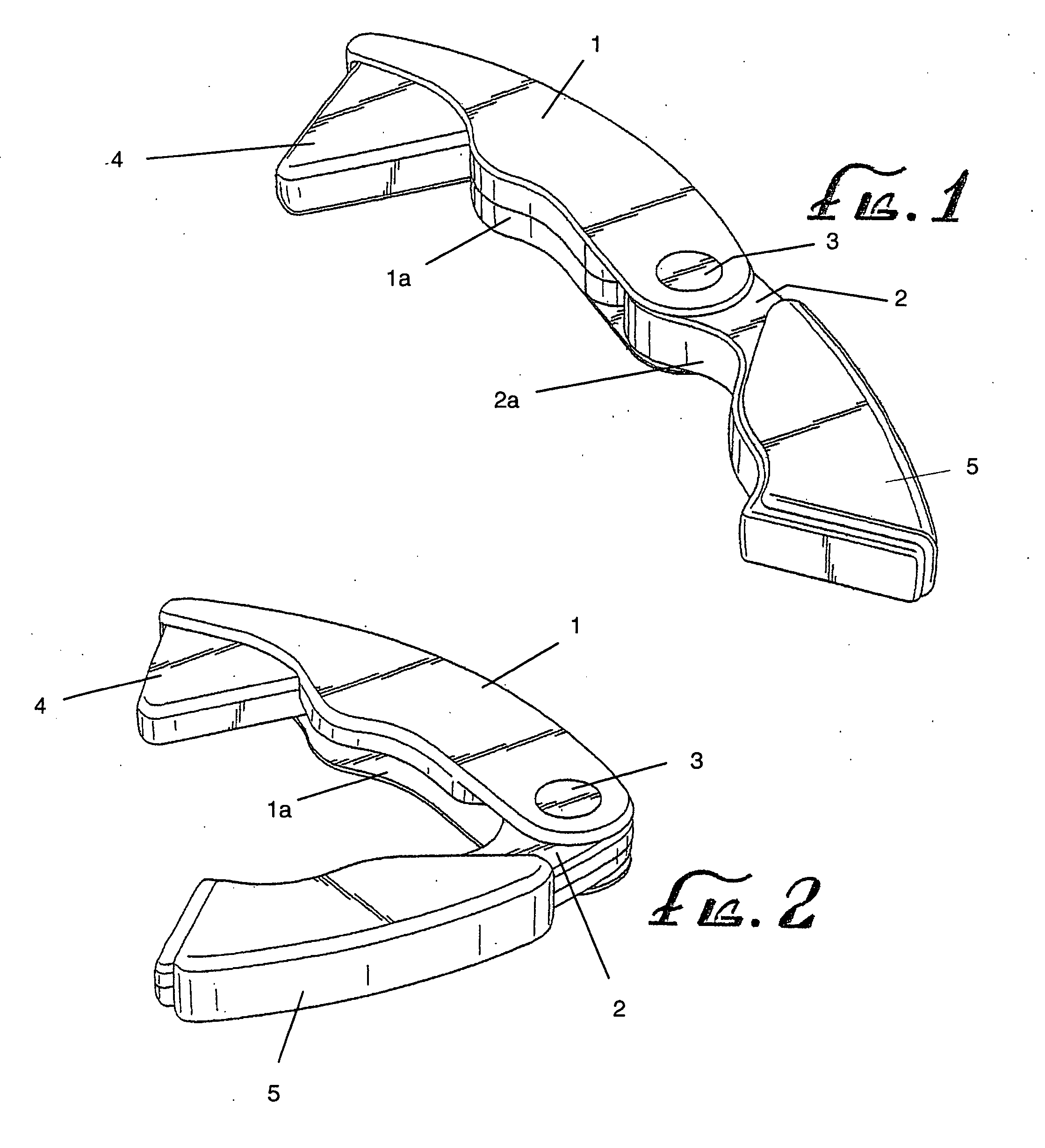
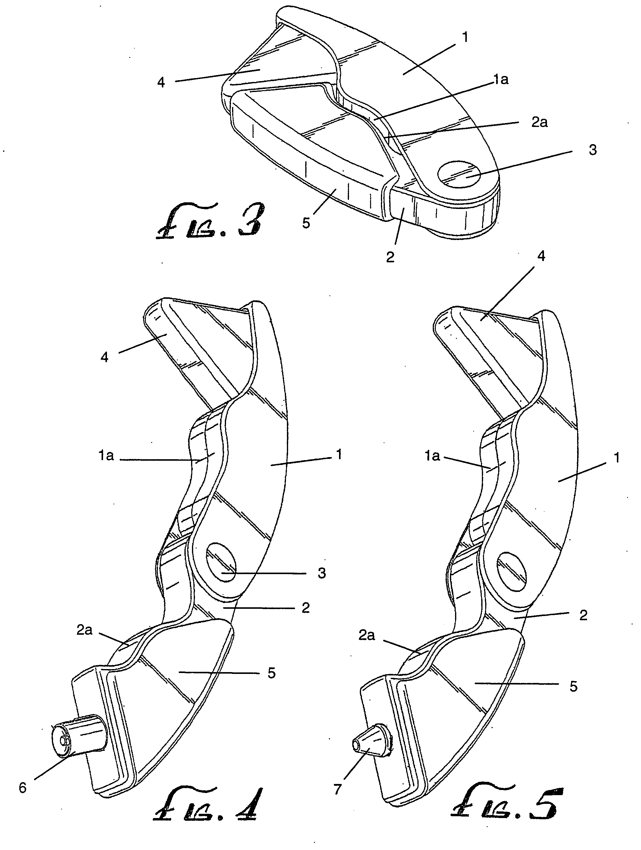
[0011] A further object of the invention will be to provide the practitioner with a reflex hammer that serves many different yet essential purposes. For example, the contemplated reflex hammer device may further include a flashlight or a writing implement as an integral component within or extending from its structure. Similarly, a neurological probe or similar device may extend from and retract into one of the folding legs of the reflex hammer. As such, the invention imparts increased utility and purpose.
[0015] In a similar fashion, the first leg may house or otherwise incorporate a secondarily functional tip. An example of such an element would be a pointed neurological probe which extends from or may be retracted into an orifice on the outboard end of the first end of the invention. By increasing the functionality of the reflex hammer, the present invention improves both the desirability and corresponding marketability of the object.
[0016] The sensitivity adjustment is achieved through the use of a sliding lever on the handle which is affixed to a tensioning device, in turn attached to the striking hammer. In the case of the sensitivity adjustment embodiment, the striking head element would be an alternate construction, such as a hollow polymer or rubber type of structure. By increasing the tension on a tensioning device, such as a tensioning cord, the striking head is compressed, thereby increasing its stiffness. As the stiffness of the striking head is increased or decreased, so varies the sensitivity of the instrument.

Problems solved by technology

This design is but a minor improvement over the conventional steel handled implement and remains a cumbersome and unwieldy device.
Such a design only marginally improves the functionality, as it would be the patient, rather than the medical provider, who typically might require a shoehorn in an examination room.
This only serves to increase the chances of the patient inadvertently leaving the office with the device still in their possession, causing the physician to search for a replacement device upon arrival of a subsequent patient.
While perhaps an improvement upon the most basic design, this device is lacking, however, as it further contributes to the increased size and weight of the hammer.
Moreover, the power source for the device is subject to limited battery life, which raises the specter of an inoperative instrument in the examination room.
Such a combination, however, results in a particularly gangly device, due to the extreme difference between the configuration of a stethoscope, with its extended tubes and earpieces, on the one hand, and the reflex hammer, on the other hand, with its basic construction of a handle and a striking end.
Such construction would be destined to create problems for the user if any of the disassembled components become lost, broken or misplaced.
While some inventions have been introduced to promote additional functions as incorporated with the basic hammer, do date these inventions have done little to render a practical device.
Instead, these devices have created even more unwieldy products through the incorporation of unnecessary, dissimilar or unwanted secondary functions.
While some devices presently known may incorporate this function, in order to do so these devices require additional bulky structure, such as electrically powered signal generation or conversion mechanisms.

Method used


Image

  • Reflex hammer
  • Reflex hammer
  • Reflex hammer

Examples


Embodiment Construction

[0029] The invention described herein comprises a folding instrument which is utilized by health care professionals for patient testing and diagnostic purposes. One of the most basic medical tests performed daily in examination rooms is the patient's reflex test typically at the knee, elbow or other similar neurological sites. To conduct the test, the physician strikes the patient sharply yet lightly, with an hammer that typically has a soft striking head. In order to render this reflex hammer more convenient, useful and desirable, the present invention takes the product from an unwieldy and cumbersome device and brings to fruition an updated, folding multi-functional device.

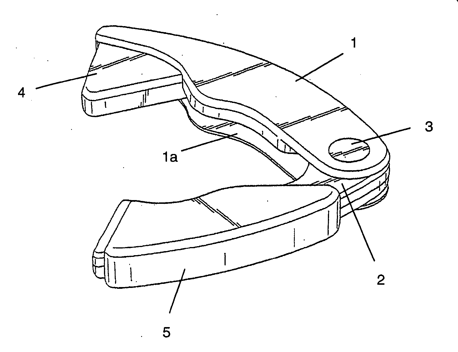
[0030] In a preferred embodiment, the folding hammer is essentially comprised of three parts. Referring to FIGS. 1-3, the preferred embodiment comprises a first elongated leg 1, and a second elongated leg 2, which are pivotally connected by a pivot pin 3. The pivot pin 3 permits the legs to fold in a fashion si...


PUM


Abstract

A folding reflex hammer includes two pivotally connected legs, one of which has the reflex testing head mounted on its inwardly facing side. The hammer is well suited to being carried by a physician or technician in any pocket due to its relatively small size when folded. In further embodiments, the folding reflex hammer may include the reflex testing device on one folding leg while the second folding leg may include additional functional implements, such as a writing implement. Other secondary implements, such as a neurological probe, may further be located within or may extend outwardly from the reflex testing head leg end. The hammer, having numerous large and generally flat sides, may further include imprinted areas for the purposes of advertising or promotion.

Description

FIELD OF THE INVENTION [0001] The present invention is directed toward the improvement of one of the most commonly used devices in the medical profession. More specifically, the present invention is directed to a reflex hammer designed to be foldable and thereby readily portable and accessible to the practitioner. The present invention is also directed toward a reflex hammer which may incorporate additional functional features arising from its integration of secondary implement tips, probes or the like. BACKGROUND OF THE INVENTION [0002] Reflex hammers have long been used in the medical profession. During most examinations, the physician, nurse or technician reaches for a reflex hammer to test the patients reflexes as a simple health or illness evaluation tool. The basic reflex hammer has typically consisted of only a flexible knob testing head attached to an elongated handle, which is swung like a hammer, as implied by the name. In its essence, the reflex hammer has changed little ...

Claims


Application Information

Patent Timeline
IPC IPC(8): A61B19/00
CPCA61B9/00
Inventor BHAVNANI, DILIP
Owner SUN COAST MERCHANDISE
Learn More