Navicular fixation device

a fixation device and navicular technology, applied in the field of navicular bone fixation devices, can solve the problems of difficult diagnosis of navicular stress fractures, bone failure, and particularly susceptible navicular stress fractures

Inactive Publication Date: 2006-10-19
DEPUY PROD INC
View PDF12 Cites 62 Cited by
  • Summary
  • Abstract
  • Description
  • Claims
  • Application Information

AI Technical Summary

Benefits of technology

[0011] In the preferred embodiment, the hook shape of the dorsal section includes a first portion adjacent the medial section that is bent at a first radius and a second portion bent at a second radius less than the first radius. The first section helps provide a transition to the hook shape, while the hook shaped second section is useful in holding the fragments of the navicular bone together.

Problems solved by technology

The navicular is particularly susceptible to stress fractures in physically active persons.
Physical activities involving repetitive foot strikes, especially those involving antagonistic muscle load, are thought to eventually result in bone failure.
The onset of navicular stress fractures are often difficult to diagnose.
However, until a positive diagnosis is made, repeated physical activity results in increased stress and bony resorption focused at the central one-third of the bone, eventually resulting in a vertical fracture of the navicular.
However, in some cases, the conservative treatment fails to achieve union of the fracture.
More severe injuries involving a displaced fracture or fragmentation cannot be treated by the conservative methods and require surgical intervention.
Where the fracture is fragmented, multiple screws / pins are required, which significantly complicates the procedure and increases the risk of non-union.
In the case of severely comminuted fractures, screws / pins are inadequate to align and reduce the bone fragments.

Method used


Image

  • Navicular fixation device
  • Navicular fixation device
  • Navicular fixation device

Examples


Embodiment Construction

[0018] For the purposes of promoting an understanding of the principles of the invention, reference will now be made to the embodiments illustrated in the drawings and described in the following written specification. It is understood that no limitation to the scope of the invention is thereby intended. It is further understood that the present invention includes any alterations and modifications to the illustrated embodiments and includes further applications of the principles of the invention as would normally occur to one skilled in the art to which this invention pertains.

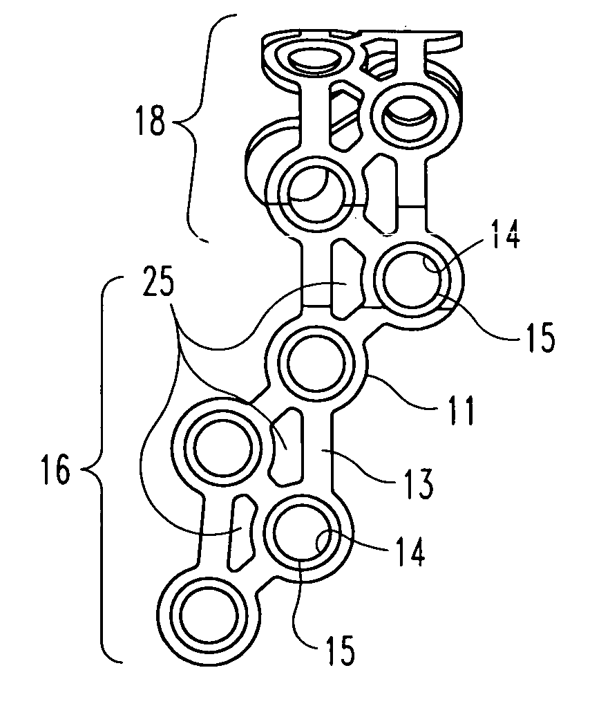
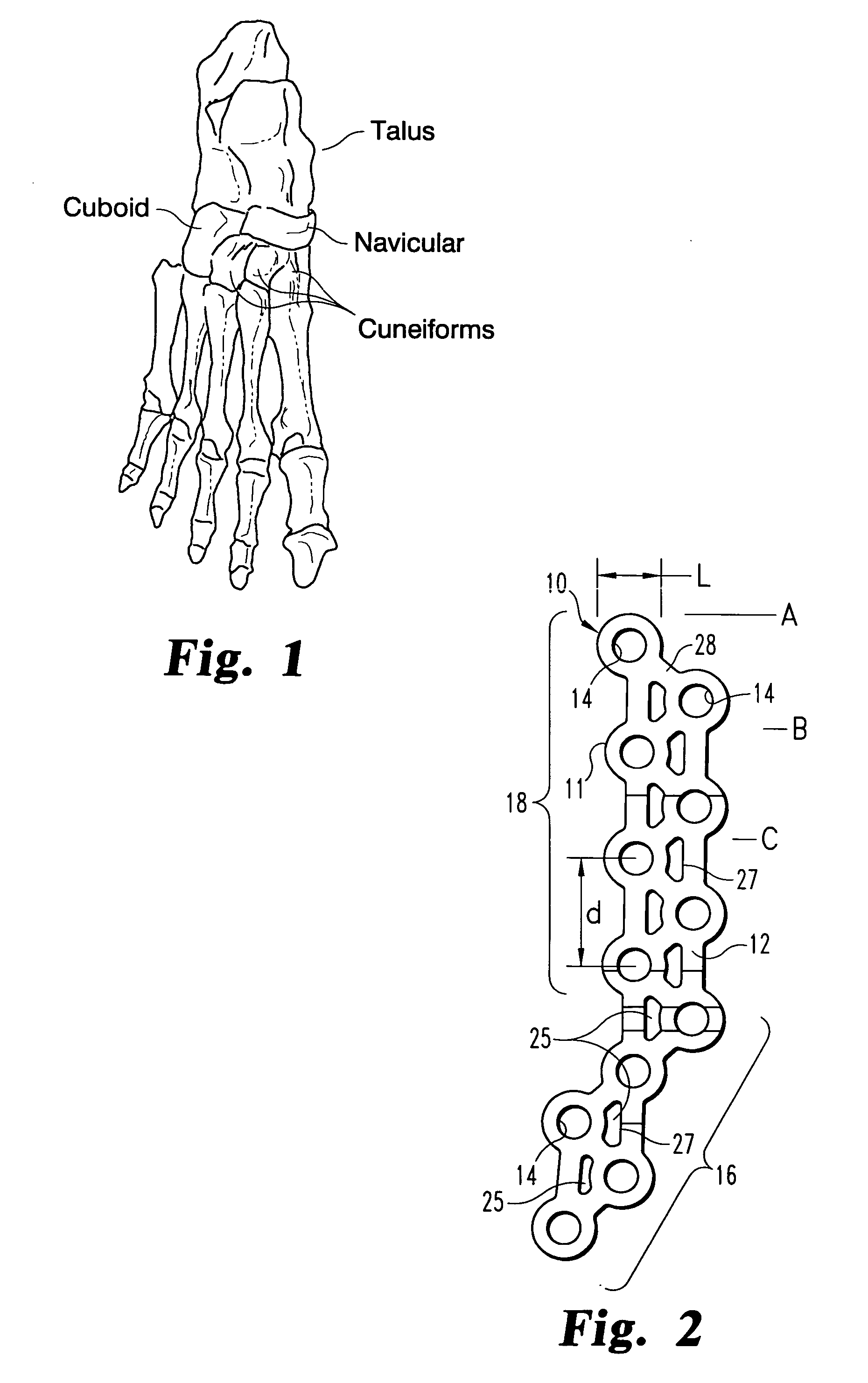
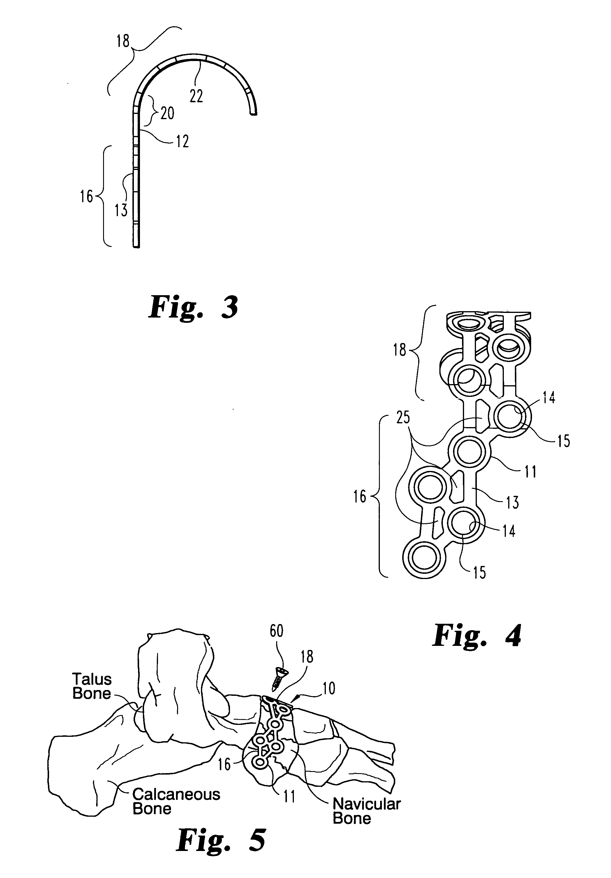
[0019] The present invention provides a navicular fixation device 10 in the form of a truss plate 11, as shown in FIGS. 2-4. The plate is formed of a medical grade material, such as a biocompatible metal. In the preferred embodiment, the metal is a titanium alloy, such as Ti-6Al-4V. Since the truss plate 11 is intended to be a permanent implant, it is desirable to minimize the prominence of the plate above the...


PUM


Abstract

A device for fixation of the navicular bone of the foot includes a truss plate defining a plurality of holes for receive bone screws therethrough. The holes are staggered along the length and width of the plate to minimize the overall width of the plate and to ensure that bone screws passing through all holes do not conflict within the bone. The plate includes a medial section configured for attachment to the medial aspect of the navicular and a dorsal section that is curved into a hook shape for attachment to the dorsal aspect of the bone. The hook shape helps retain and reduce the bone fragments of a fractured navicular. The plate further defines a plurality of cut-outs between struts supporting the screw hole locations, wherein the cut-outs are configured to receive bone fasteners therethrough.

Description

BACKGROUND OF THE INVENTION [0001] The present invention relates to fixation devices for the bones of the foot, and particularly for the navicular bone. The invention is especially suitable for reducing comminuted fractures of the navicular. [0002] The foot is formed by a complex array of bones and ligaments that all present unique signatures when injured. The navicular bone is situated between the talus and the cuneiform bones and medially adjacent the cuboid, as shown in FIG. 1. The navicular serves as an anchor for medial or internal ligaments of the ankle, as well as for ligaments connected to the cuboid and metatarsal bones. The navicular is particularly susceptible to stress fractures in physically active persons. For instance, during foot strike, the navicular bone is impinged between the proximal talus and the distal cuneiforms, with most of the force focused at the central one-third of the bone. The risk of stress fracture of the navicular is aggravated by the fact that thi...

Claims


Application Information

Patent Timeline
Patent Type & Authority Applications(United States)
IPC IPC(8): A61F2/30
CPCA61B17/8061
Inventor SANDERS, ROYPRASAD, PRIYABREMER, CHRIS
Owner DEPUY PROD INC
Why Eureka
Try Eureka