Air blowing device for printing press

a printing press and air blowing technology, which is applied in the field of air blowing devices for printing presses, can solve the problems of low registration accuracy, double moisture absorption, and fan out phenomenon, and achieve the effect of preventing printing trouble and improving printing quality

Inactive Publication Date: 2006-10-26
KOMORI CORP
View PDF6 Cites 0 Cited by
  • Summary
  • Abstract
  • Description
  • Claims
  • Application Information

AI Technical Summary

Benefits of technology

[0007] It is an object of the present invention to provide an air blowing device for a printing press, which prevents a printing trouble and improves the printing quality simultaneously.

Problems solved by technology

Consequently, patterns that should overlap are printed with registration errors to lower the registration accuracy, causing a so-called fan-out phenomenon.
The fan-out phenomenon becomes typical to cause a major printing trouble in a double-sided printing press which prints the obverse and reverse sides of a printing sheet simultaneously, because the moisture to be absorbed doubles.
The air blown to the surface of the roller flows in even to behind the roller to flutter the printing sheet under conveyance or cause a gripping change error of the printing sheet, leading to jamming or a trouble of the printing press.
Also, the air that has flown in even to behind the roller to reach the plate cylinder may vaporize the originally necessary moisture on the plate cylinder to degrade the printing quality.
This causes striped density nonuniformities on the printing surface of a printing sheet 44 to degrade the printing quality.

Method used


Image

  • Air blowing device for printing press
  • Air blowing device for printing press
  • Air blowing device for printing press

Examples


Embodiment Construction

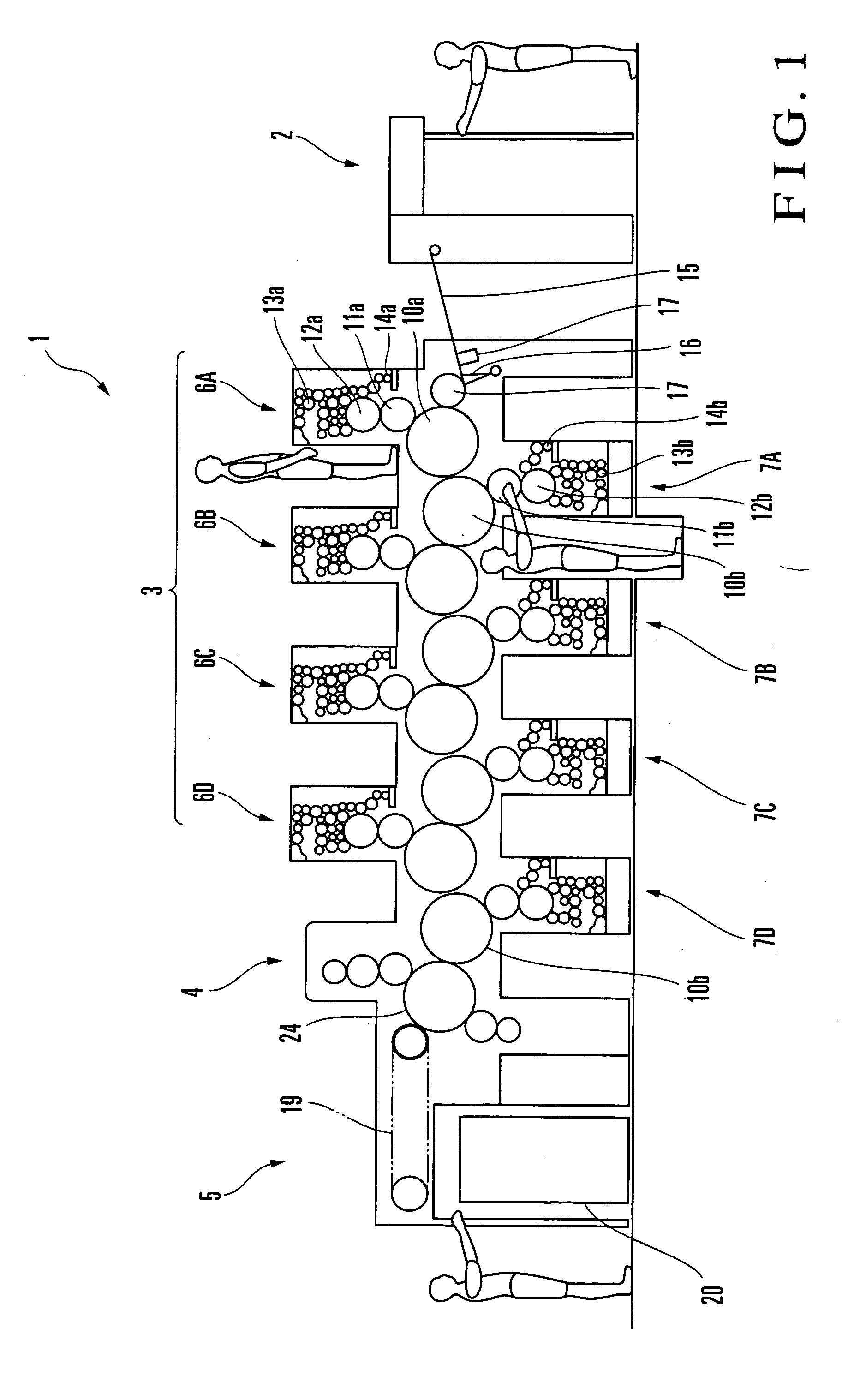
[0015] An air blowing device for a printing press according to one embodiment of the present invention will be described with reference to FIGS. 1 to 4. Referring to FIG. 1, a sheet-fed offset rotary printing press 1 comprises a feed device 2 which feeds a sheet for printing, a printing unit 3 which prints on the sheet fed from the feed device 2, a coating unit 4 which coats the obverse and reverse surfaces of the sheet printed by the printing unit 3 with varnish, and a delivery unit 5 which delivers the sheet coated by the coating unit 4. The printing unit 3 comprises four obverse surface printing units 6A to 6D which print on the obverse surface of the sheet, and four reverse surface printing units 7A to 7D which print on the reverse surface of the sheet.

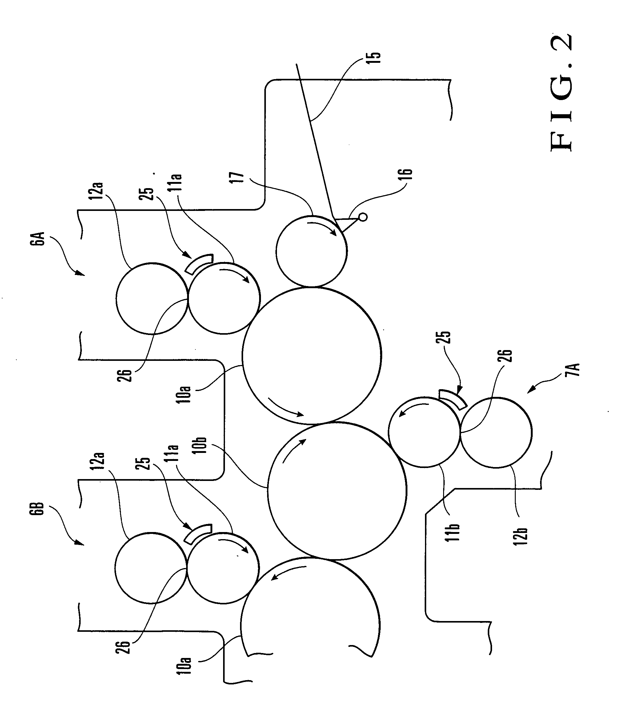
[0016] Each of the obverse surface printing units 6A to 6D includes an impression cylinder 10a serving as a double-sized diameter printing cylinder which has grippers on its outer surface to grip the sheet, a blanket cylinder 11a...


PUM


Abstract

An air blowing device for a printing press includes a plate cylinder, blanket cylinder, impression cylinder, air blowing equipment, air suction equipment, and cover. The plate cylinder is rotatably supported. Ink from an inking device and dampening water from a dampening device are supplied to the outer surface of the plate cylinder. The blanket cylinder is rotatably supported in contact with the plate cylinder. The impression cylinder is rotatably supported in contact with the blanket cylinder and cooperates with the blanket cylinder to print on a printing target body under conveyance. The air blowing equipment discharges air from one end side toward the other end side of the blanket cylinder. The air suction equipment takes in air, discharged from the air blowing equipment, at the other end side of the blanket cylinder. The cover forms an air passage extending from the air blowing equipment to the air suction equipment in an axial direction of the blanket cylinder.

Description

BACKGROUND OF THE INVENTION [0001] The present invention relates to an air blowing device for a printing press, which vaporizes dampening water which has spread onto a blanket cylinder through a plate cylinder. [0002] Generally, in an offset printing press, ink that is supplied to the plate surface of a printing plate mounted on a plate cylinder is once transferred to the blanket of a blanket cylinder and then to a printing sheet. At this time, dampening water is supplied in addition to the ink, so the ink attaches only to an image area and not to a non-image area. The dampening water spreads from the plate surface onto the blanket surface and then to the printing sheet sequentially. The printing sheet that has absorbed moisture tends to elongate horizontally and vertically. Particularly, in the case of multi-color printing, each time the printing sheet passes through a printing unit, the printing sheet absorbs moisture and elongates. Hence, a pattern that is printed earlier elongat...

Claims


Application Information

Patent Timeline
Patent Type & Authority Applications(United States)
IPC IPC(8): B41F3/52B41F23/00
CPCB41F22/00B41F13/22
Inventor SHIMIZU, YOU
Owner KOMORI CORP
Why Eureka
Try Eureka