Thermal Printhead

a printhead and thermal technology, applied in printing and other directions, can solve the problems of ink not being properly transferred, wrinkles in ink ribbons, etc., and achieve the effect of preventing wrinkles and preventing print failur

Inactive Publication Date: 2008-10-02
ROHM CO LTD
View PDF0 Cites 0 Cited by
  • Summary
  • Abstract
  • Description
  • Claims
  • Application Information

AI Technical Summary

Benefits of technology

[0010]An object of the present invention, which is conceived under the above-described circumstances, is to provide a thermal printhead which is capable of preventing wrinkles from being formed in an ink ribbon and hence preventing the print failure caused by such wrinkles in the ink ribbon.

Problems solved by technology

Also for this reason, a force corresponding to the transferring force of the platen roller P is exerted on the ink ribbon R in the direction opposite from the secondary scanning direction x, which may result in the formation of wrinkles in the ink ribbon R. When the ink ribbon R is wrinkled and hence folded, ink cannot be properly transferred from the folded portion of the ink ribbon R to the recording sheet S, which results in print failure.

Method used


Image

  • Thermal Printhead
  • Thermal Printhead
  • Thermal Printhead

Examples


first embodiment

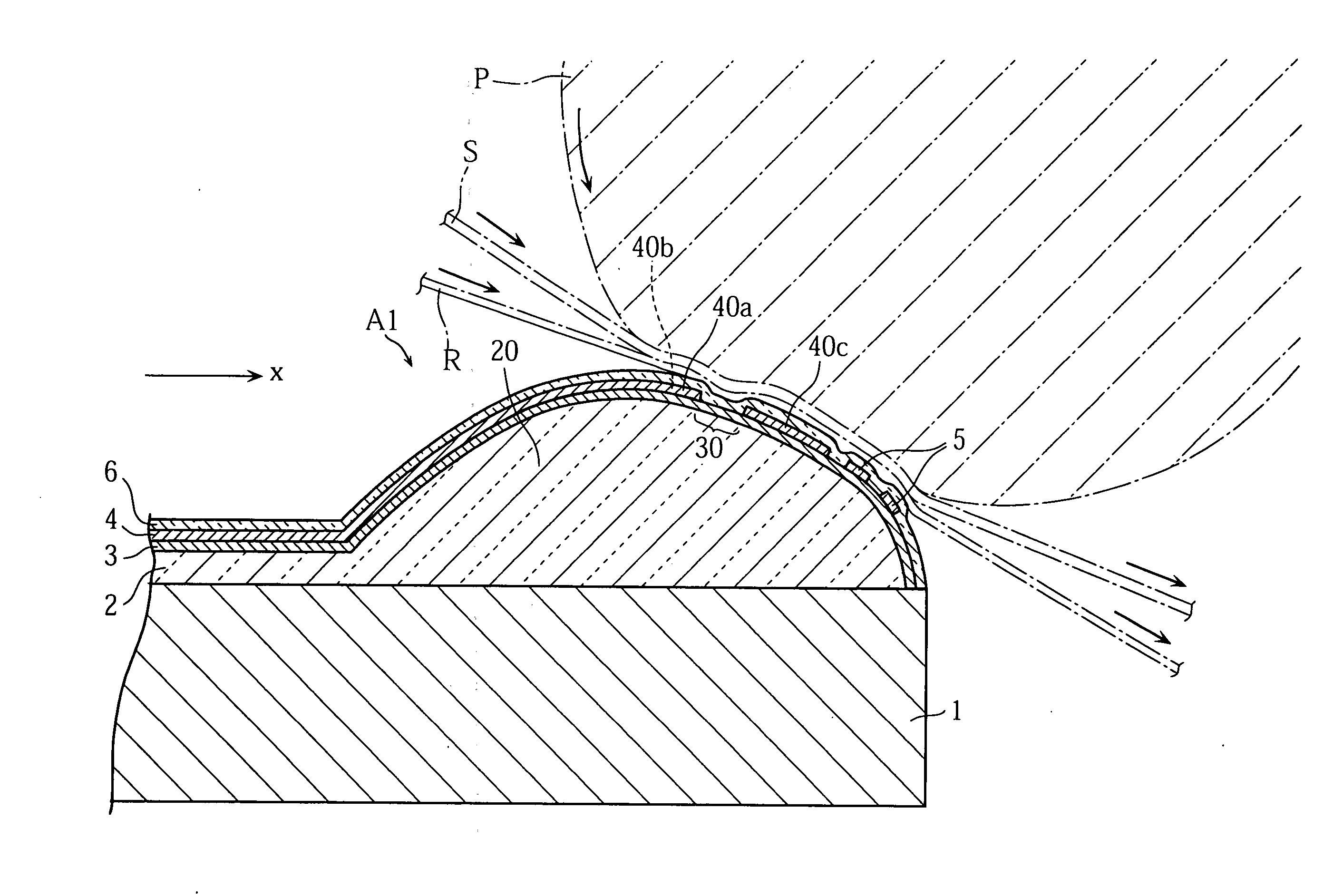
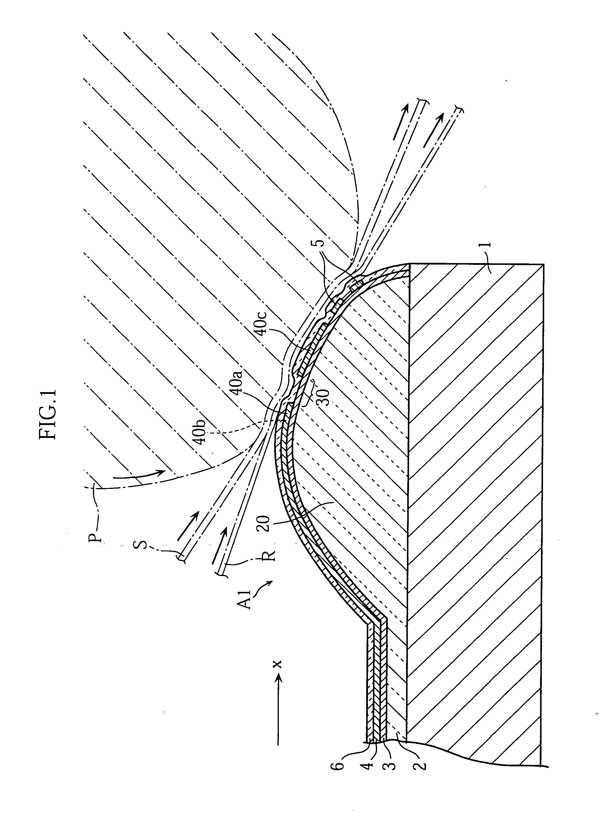
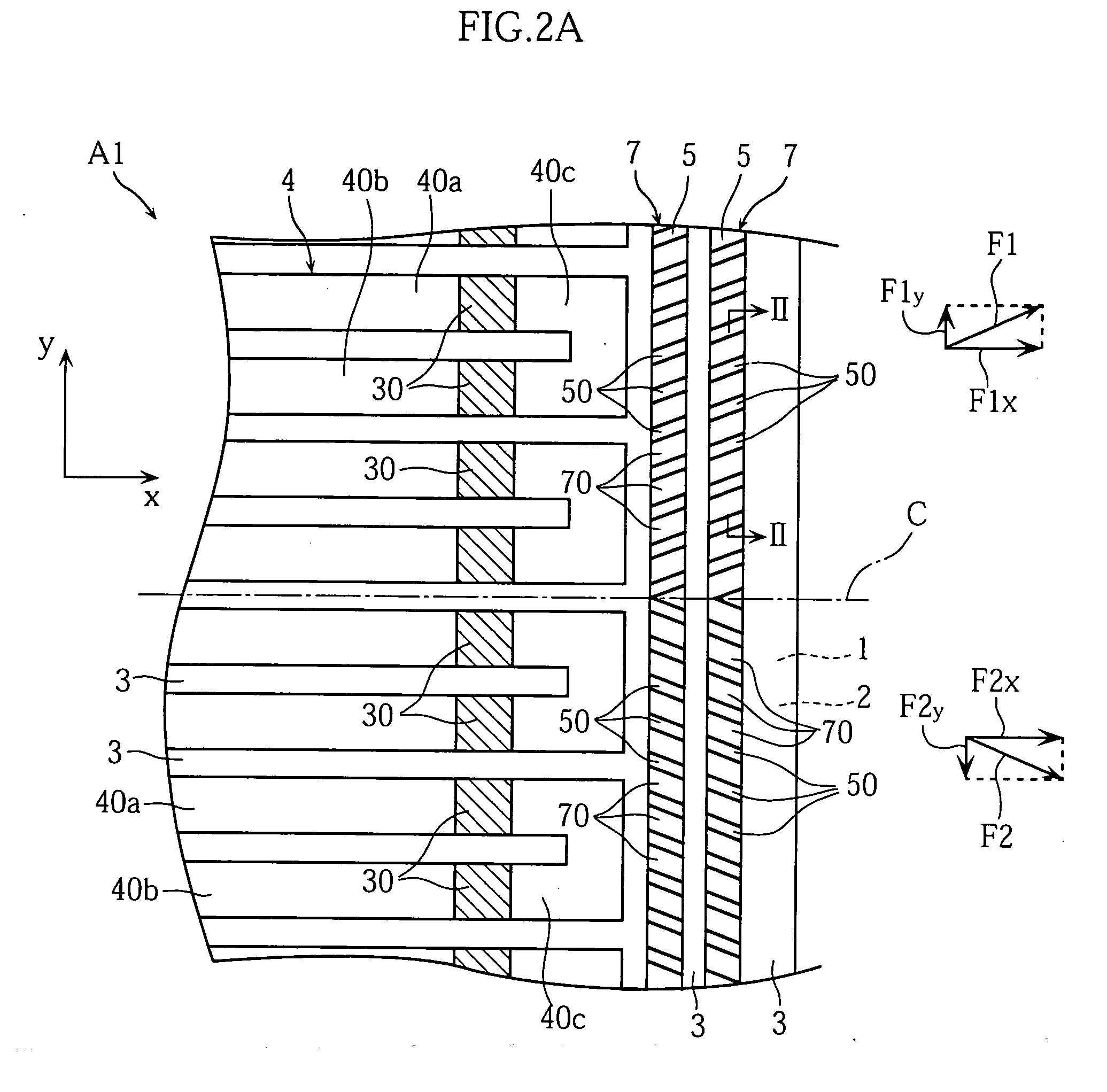
[0023]FIGS. 1, 2A and 2B show a thermal printhead according to the present invention. In FIG. 2A, the illustration of a protective layer indicated by the reference sign 6 in FIG. 1 is omitted.

[0024]As shown in FIG. 1, the thermal printhead A1 according to the first embodiment includes a substrate 1, a glaze layer 2, a resistor layer 3, an electrode layer 4, two strips of edge patterns 5, and a protective layer 6.

[0025]The thermal printhead A1 utilizes a platen roller P for printing. Specifically, a recording sheet S and a thermal ink ribbon R are supplied between the platen roller P and the thermal printhead A1, and printing on the recording sheet S is performed while transferring the recording sheet S and the ink ribbon R in a secondary scanning direction x. The surface portion of the platen roller P is made of rubber, for example, so that it deforms upon contact with the thermal printhead A1 due to the contact pressure.

[0026]The substrate 1 is a ceramic insulating substrate in the...

second embodiment

[0043]However, each of the projections 70 serves to guide the ink ribbon R in the primary scanning direction y, and when a force to shrink the ink ribbon R in the primary scanning direction y toward the center line C is generated in transferring the ink ribbon R, a resisting force against such a force is generated at each of the projections 70. Therefore, in the second embodiment again, the formation of wrinkles in the ink ribbon R is prevented.

[0044]As will be understood from the second embodiment and the first embodiment, the formation of wrinkles of the primary scanning direction y in the ink ribbon R is effectively prevented whether or not the projections 70 of the inequality surface region 7 are inclined with respect to the center line C. Therefore, projections 70 inclined with respect to the center line C and those which are not inclined may be mixedly provided. The angle of inclination relative to the center line C may be different among the projections.

[0045]FIG. 4 shows a t...

third embodiment

[0051]For instance, the inequality surface region 7 on the downstream side of the third electrode portions 40c in the secondary scanning direction x may be formed without utilizing edge patterns 5. In a structure which does not include edge patterns 5 like the thermal printhead A2 of the third embodiment, the inequality surface region 7 may be provided by alternately forming projections and recesses at part of the protective layer 6. To reliably prevent the formation of wrinkles in the ink ribbon, it is preferable to make the area of the inequality surface region 7 as large as possible. However, the present invention is not limited thereto, and the area is not limited to be specified.

[0052]The pattern of electrodes of the thermal printhead is not limited. The present invention is also applicable to a thermal printhead which includes a common electrode with so-called comb-tooth portions. Moreover, the present invention is applicable to both of a thick-film thermal printhead and a thi...


PUM


Abstract

A thermal printhead (A1) includes a substrate (1) and a plurality of heat-producing resistance sections (30) provided on the substrate (1). The heat-producing resistance sections (30) melt ink of an ink ribbon, which is transferred together with a recording sheet, to transfer the ink onto the recording sheet. An inequality surface region (7) is provided downstream from the heat-producing resistance sections (30) in a secondary scanning direction (x) which is the transfer direction of the ink ribbon. The inequality surface region includes a plurality of projections (70) each of which extends in the secondary scanning direction (x) and which are aligned at predetermined intervals in a primary scanning direction (y) which is perpendicular to the secondary scanning direction (x).

Description

TECHNICAL FIELD[0001]The present invention relates to a thermal printhead suitable for printing using a thermal ink ribbon.BACKGROUND ART[0002]FIG. 5 shows an example of a thermal printhead as related art. The illustrated thermal printhead B includes an insulating substrate 90 on which a glaze layer 91, a resistor layer 92, an electrode layer 93 and a protective layer 94 are successively formed.[0003]The electrode layer 93 includes a plurality of electrode portions 93a and a plurality of electrode portions 93b which are spaced from each other to provide a gap therebetween where the electrode layer does not overlap the resistor layer 92. Of the resistor layer 92, the portion corresponding to the gap between the electrode portions 93a and the electrode portion 93b serves as a heat-producing resistance section 92a which is heated when energized. The heat-producing resistance section 92a is located on a bulging portion 91a of the glaze layer 91 against which a recording sheet S and an i...

Claims


Application Information

Patent Timeline
Patent Type & Authority Applications(United States)
IPC IPC(8): B41J2/335
CPCB41J2/33565B41J2/32B41J2/335
Inventor NAKANISHI, MASATOSHI
Owner ROHM CO LTD
Why Eureka
Try Eureka