Canard position and dihedral for boom reduction and pitch/directional control

Active Publication Date: 2006-10-26
SUPERSONIC AEROSPACE INT
View PDF1 Cites 18 Cited by
  • Summary
  • Abstract
  • Description
  • Claims
  • Application Information

AI Technical Summary

Benefits of technology

[0007] What are desired are an aircraft and constituent components that enable supersonic flight by applying new technologies and an innovative aircraft design approach. What is further desired is an aircraft that can significantly reduce travel times, for example by a factor of two through supersonic cruise speed capabilit

Problems solved by technology

Technology advances have produced longer range, safer, and more comfortable aircraft—but not faster flights.
Many of the desirable features of supersonic civilian aircraft, particularly low-boom performance and long range, are very difficult to attain.
The difficulty

Method used


Image

  • Canard position and dihedral for boom reduction and pitch/directional control
  • Canard position and dihedral for boom reduction and pitch/directional control
  • Canard position and dihedral for boom reduction and pitch/directional control

Examples


Embodiment Construction

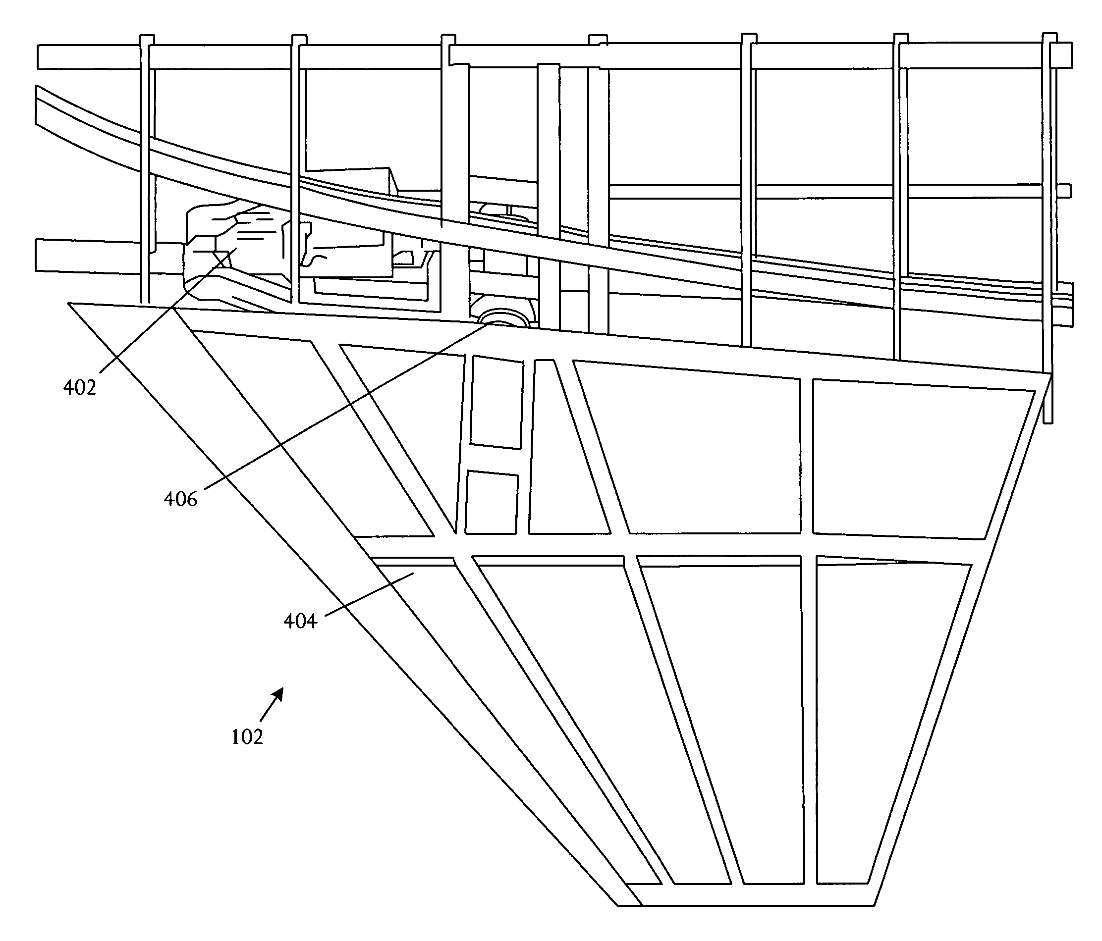
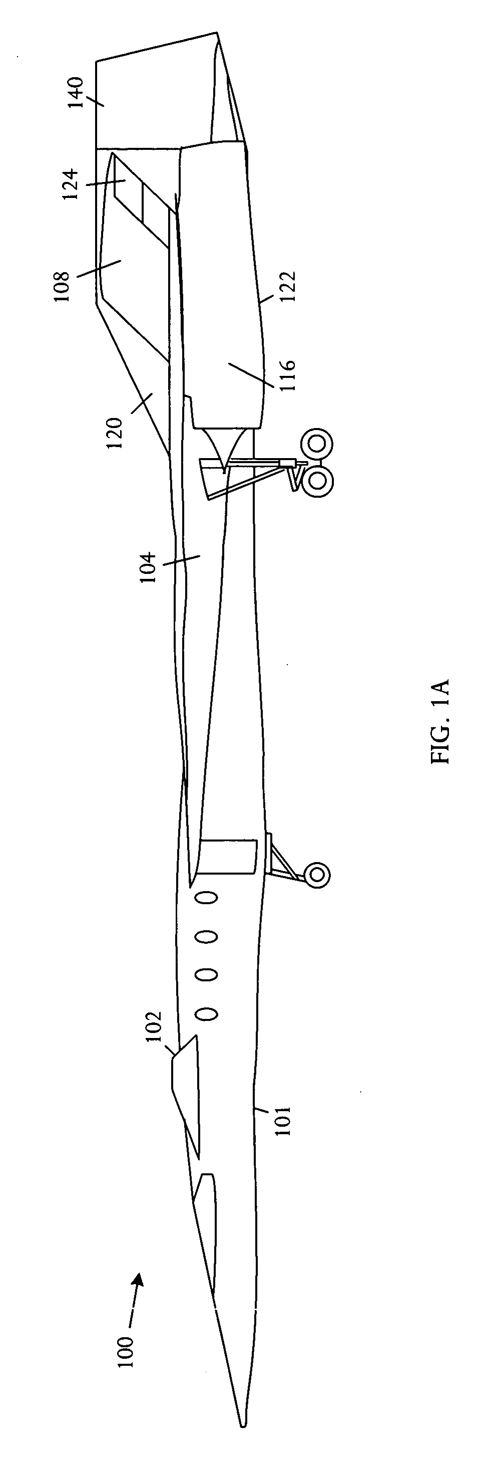
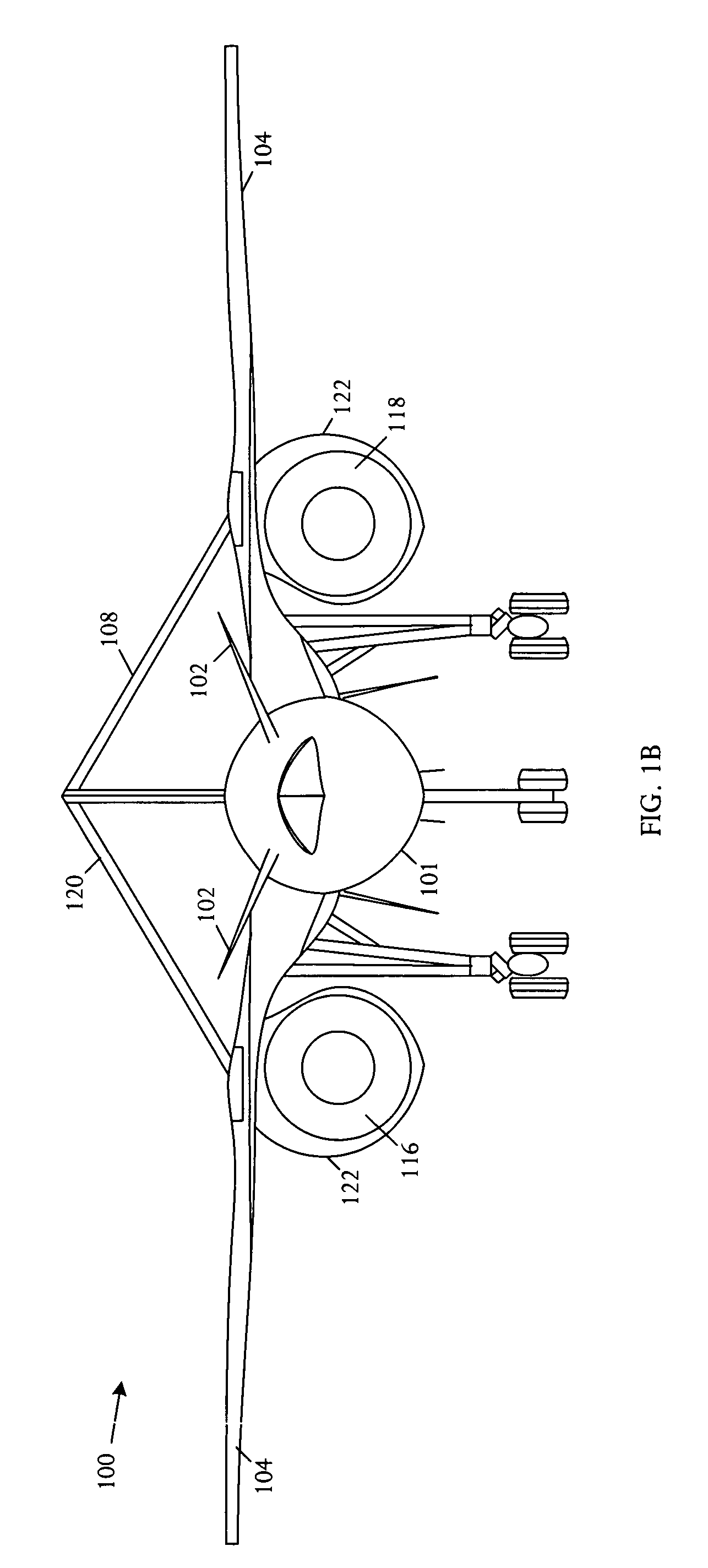
[0024] Referring to FIGS. 1A, 1B, and 1C, schematic pictorial diagrams respectively showing side, front, and top views of an embodiment of a supersonic aircraft 100. The aircraft 100 comprises the fuselage 101 extending forward and aft along a longitudinal axis and having a lower surface and an upper surface. A wing 104 is coupled to the fuselage 101. The aircraft 100 has a canard 102 coupled onto the fuselage 101 at a position forward of the wing 104 at an elevated location. The elevated positioning of the canard 102 on the fuselage 101 enables stretching of the aircraft lifting length, resulting in an effective area distribution that attains a shaped sonic boom signature.

[0025] The canards 102 have a dihedral that is sufficiently high to increase the aircraft lifting length and attain a target equivalent area distribution for low sonic boom performance. The canard 102 operates as a longitudinal power control device that is particularly effectively during takeoff and in high-speed...


PUM


Abstract

A supersonic aircraft comprises a fuselage extending forward and aft, wings coupled to lateral sides of the fuselage, and canards coupled to lateral sides of the fuselage forward of the wings. The individual canards are configured to generate shocks that wrap around the fuselage and intersect with wing leading edges on opposing sides of the fuselage.

Description

BACKGROUND OF THE INVENTION [0001] The global economy makes long range business travel more essential than ever. However, other than Concorde, with presence declining as transatlantic flights have discontinued, the pace of business travel remains at 1960's-era speeds. Technology advances have produced longer range, safer, and more comfortable aircraft—but not faster flights. [0002] Supersonic overland capability and range are drivers of market potential for aircraft in the commercial and business sector. Buyers of supersonic commercial aircraft are expected to be from entities such as corporations, governments and government agencies, and high net-worth individuals. Most operators are expected to be large organizations, for example corporations and governments, with sophisticated flight departments that can manage multiple aircraft types. Flights are expected to depart and arrive in a wide range of environments, from large international and national airports to small local airfields...

Claims


Application Information

Patent Timeline
IPC IPC(8): B64C1/40B64C30/00B64C3/16B64C5/02B64C5/04B64C5/10B64C5/12B64C7/00B64C9/22B64C9/32B64C9/36B64C13/42B64C13/50B64C23/04B64C39/12
CPCB64C3/16Y02T50/32B64C5/04B64C5/10B64C5/12B64C7/00B64C9/22B64C9/32B64C9/323B64C9/36B64C13/42B64C13/503B64C23/04B64C30/00B64C39/12Y02T50/12B64C5/02B64C13/505Y02T50/10Y02T50/30
Inventor CUCCIAS, ROBERT S.MORGENSTERN, JOHN M.ARSLAN, ALAN E.LEE, HOWARD
Owner SUPERSONIC AEROSPACE INT
Why Eureka
Try Eureka