Method for regulating the time constant matching in DC/DC converters

a time constant matching and converter technology, applied in the direction of electric variable regulation, ac network voltage adjustment, instruments, etc., can solve the problems of high component cost, high precision required, and jeopardizing the reading precision and thus the current estimate, so as to achieve simple and quick effect, low dependen

Inactive Publication Date: 2006-10-26
STMICROELECTRONICS SRL
View PDF4 Cites 5 Cited by
  • Summary
  • Abstract
  • Description
  • Claims
  • Application Information

AI Technical Summary

Benefits of technology

[0031] A first embodiment of the present invention provides a method for regulating the time constant matching in such a manner to equalize the time constant of the reading network with that of the coil network in a simple and quick way, with a lower dependence on the temperature and the aging of the components and which allows the use of common components and having such functional characteristics as to allow to overcome the limits still affecting the methods according to the prior art.

Problems solved by technology

The use of this method however introduces a drawback due to the real value offset of the components employed by the respective nominal value, jeopardizing the reading precision and thus the current estimate.
Thus, against a variation of the current required by the load, such difference can cause, on the DC / DC converter regulated output voltage, overelongations or subelongations which can jeopardize the tolerance band imposed by the specifications.
Such solution however implies extremely high component costs linked to the precision required and, moreover, the use of such components also implies high costs in terms of area occupied on the motherboard.
However, systems with such a high number of phases are out of the normal trend for DC / DC converters, which require reduced costs and minimal uses of areas in the motherboard.
However, such types of COG capacitors have a more than double cost with respect to the common capacitors.

Method used


Image

  • Method for regulating the time constant matching in DC/DC converters
  • Method for regulating the time constant matching in DC/DC converters
  • Method for regulating the time constant matching in DC/DC converters

Examples


Embodiment Construction

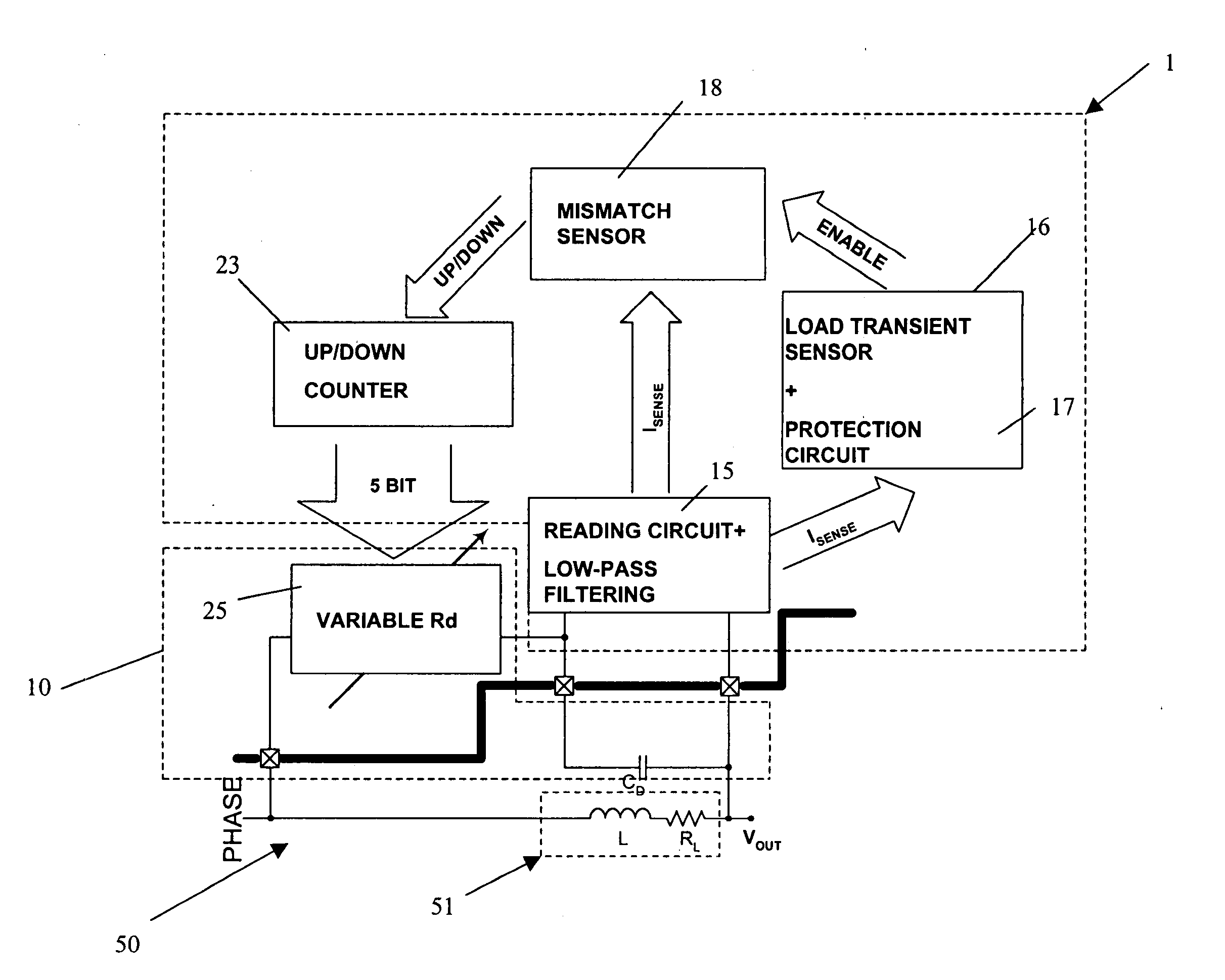
[0057] A regulation method, according to one embodiment of the present invention, is schematically shown by means of a block scheme reported in FIG. 3 and applied to a DC / DC converter phase 50.

[0058] The DC / DC converter phase 50 is associated, in a usual way, with a coil network 51 comprising a series LR circuit with an inductance L and a parasitic resistance RL.

[0059] The DC / DC converter phase 50 also provides a reading network 10 comprising an RC circuit with a capacitance CD in series with a variable resistance RD, placed in parallel to the coil network 51.

[0060] Advantageously, the capacitance CD and the resistance RD are controlled and regulated by a device which, in the block scheme, is indicated with number 1.

[0061] The device 1, allows to regulate, further to a variation of the load applied to the DC / DC converter, the time constant matching of the phase 50.

[0062] Advantageously, the regulation method according to one embodiment of the present invention is of the adaptiv...


PUM


Abstract

A method regulates the time constant matching of a DC/DC converter phase, further to a variation of a load applied to an output of said phase. Such phase being associated with a coil network, with a series RL circuit and a reading network 10, with a series RC circuit connected in parallel to the coil network. The method includes an acquisition step, suitable to acquire the trend of a voltage detected across the capacitance CD of the reading network 10, transforming it into a current trend, a detection step suitable to identify a variation above a certain threshold value of said current trend, an identification step, enabled by said detection step, suitable to determine a slope of said current trend and a regulation step suitable to adapt the value of said resistance RD based on said slope determined by said identification step.

Description

BACKGROUND OF THE INVENTION [0001] 1. Field of the Invention [0002] The present invention relates to a method for regulating the time constant matching, for example, in DC / DC converters. [0003] The invention particularly, but not exclusively, relates to a method to be used in DC / DC converters, for example in voltage regulator module (VRM) applications, and the following description is made with reference to this field of application for convenience of illustration only. [0004] The invention further relates to a corresponding regulation device for regulating and controlling the time constant matching in DC / DC converters. [0005] 2. Description of the Related Art [0006] As it is well known, the evolution of the electric characteristics of processors for PCs, WORSTATIONS and SERVERS obliges manufacturers to search for new solutions meeting the CPU requirements that include: high precision in the supply voltage, for instance + / −0.8% under steady state conditions and + / −3% under transient...

Claims


Application Information

Patent Timeline
Patent Type & Authority Applications(United States)
IPC IPC(8): G05F1/00H02J3/12
CPCH02M2001/0009H02M3/156H02M1/0009
Inventor ZAFARANA, ALESSANDROZAMBOTTI, DARIOSAGGINI, STEFANO
Owner STMICROELECTRONICS SRL
Why Eureka
Try Eureka