Systems and methods for night time surveillance

a surveillance system and night vision technology, applied in the field of surveillance systems, can solve the problems of insufficient beam intensity, narrow instantaneous field of view, and difficult for users of such surveillance cameras to orient themselves in the surveyed area, so as to reduce the field of regard

Inactive Publication Date: 2006-10-26
OPSIGAL CONTROL SYST
View PDF31 Cites 221 Cited by
  • Summary
  • Abstract
  • Description
  • Claims
  • Application Information

AI Technical Summary

Benefits of technology

[0009] Embodiments of the invention provide systems and methods for night time surveillance, including systems and methods, which provide a broad view of the surveyed area containing the current field of view. The systems and methods can enable a user to immediately understand where the current field of view is positioned, acquire the proper space orientation, and take the derived proper actions in case of threat detection. The systems and methods can also reduce the field of regard scanning time as well as the revisit time of a given point in the surveillance camera's scanned sector. In o

Problems solved by technology

Night vision cameras using infrared illuminators may provide high magnification, but this high magnification naturally results in a narrow instantaneous field of view.
The narrow field of view is also due to the fact that, at a given range, diverging the illuminator's beam beyond a certain angle will entail a beam intensity insufficient for producing a useful image.
This field of view limitation makes it difficult for users of such surveillance cameras to orient themselves in the surveyed area, especially when the area they need to cover is large and complex or when the momentary night vision view has a low information content.
Due to the nature of surveillance tasks, such a search procedure is not generally practical because it can consume valuable time in a moment of emergency.
The derived long scanning time required by a surveillance camera to cover typical angular sectors defining the field of regard of the surveillance camera can be a problem.
Using a gated imaging technology requires an expensive imager and complicated synchronization of the laser pulses with the imager.
Additionally, a gated imaging based night vision system is susceptible to saturation due to intense lig

Method used


Image

  • Systems and methods for night time surveillance
  • Systems and methods for night time surveillance
  • Systems and methods for night time surveillance

Examples


Embodiment Construction

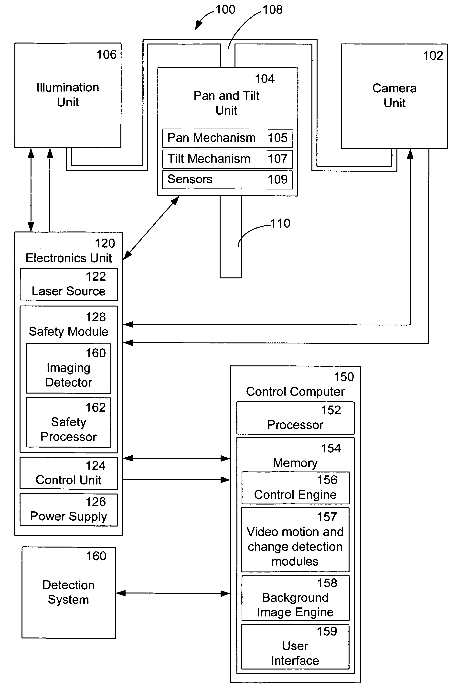
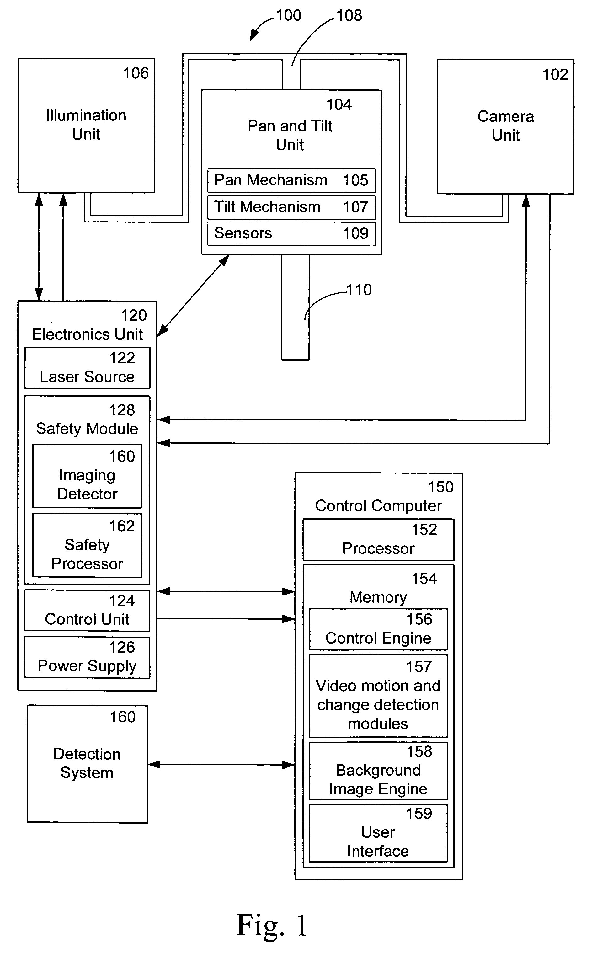
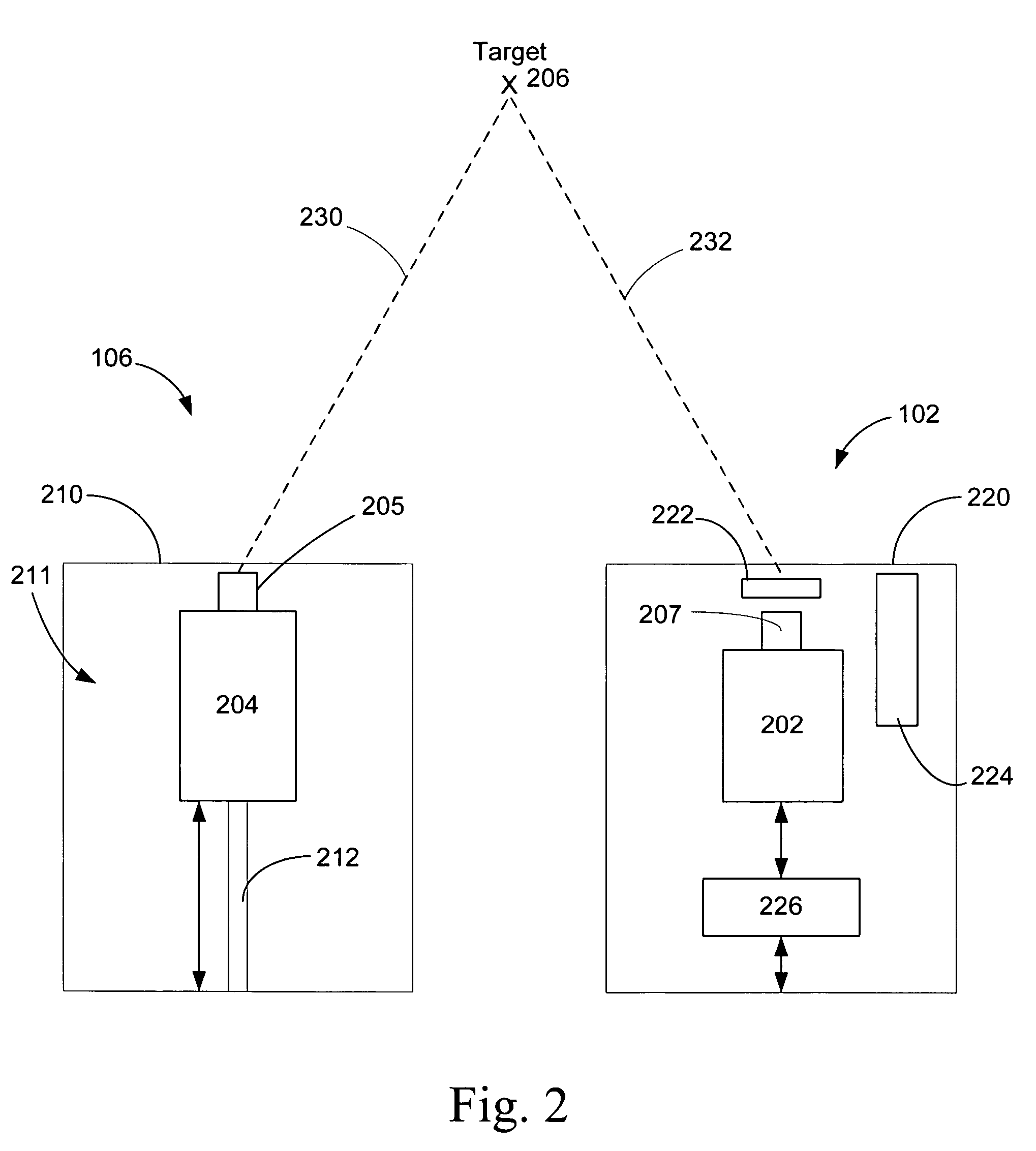
[0026] Embodiments of the invention provide systems and methods for night time surveillance. There are multiple embodiments of the present invention. By means of introduction and example, one illustrative embodiment of the present invention provides a night time surveillance system that utilizes an IR laser illuminator with a zoom collimating lens and an imager composed of a video camera and zoom lens. The optical axes of the illuminator and the imager are spatially separated to create a parallax in order to reduce atmospheric backscattering. The illumination beam from the laser illuminator may be shaped to uniformly distribute light over the whole field of view. The focal length of a collimator in the illuminator may be made to change with the focal length of the camera or they can move independently of one another. The system may also include a safety mechanism or circuit that is capable of detecting when objects are too close to the illuminator and can shut down the laser source....


PUM


Abstract

Methods and systems for surveillance are described. One described method for use in a surveillance system having a camera, comprises generating a background image of the camera's field of regard, receiving a live video image of the camera's current field of view, wherein the field of view is within the field of regard, and correlating a position of the live video image within the background image.

Description

RELATED APPLICATIONS [0001] This invention claims priority to U.S. provisional patent application No. 60 / 640,244, entitled “SYSTEM AND A METHOD FOR IMPROVING NIGHT TIME PERFORMANCE OF ACTIVE ILLUMINATION BASED SURVEILLANCE CAMERAS,” filed Jan. 3, 2005, the entirety of which is hereby incorporated by reference.FIELD OF THE INVENTION [0002] This invention relates generally to surveillance systems, and more particularly, embodiments of this invention relate to systems and methods for night vision surveillance systems. BACKGROUND OF THE INVENTION [0003] Night vision cameras using infrared illuminators may provide high magnification, but this high magnification naturally results in a narrow instantaneous field of view. The narrow field of view is also due to the fact that, at a given range, diverging the illuminator's beam beyond a certain angle will entail a beam intensity insufficient for producing a useful image. This field of view limitation makes it difficult for users of such surve...

Claims


Application Information

Patent Timeline
IPC IPC(8): H04N7/18H04N5/33H04N9/47
CPCG08B13/196G08B13/19606G08B13/19682G08B13/19689G08B13/19695H04N5/33H04N5/23216H04N5/23238H04N5/23293H04N5/272H04N5/2723H04N5/23206H04N23/661H04N23/62H04N23/632H04N23/698H04N23/635H04N23/695H04N7/18
Inventor TAMIR, MICHAEL
Owner OPSIGAL CONTROL SYST
Why Eureka
Try Eureka