Mounting system capable of adjusting viewing angle of a monitor

Inactive Publication Date: 2006-10-26
CLO SYST
View PDF0 Cites 28 Cited by
  • Summary
  • Abstract
  • Description
  • Claims
  • Application Information

AI Technical Summary

Benefits of technology

[0006] The mounting system may also include one or more motors to move the second ends of the beams substantially along the predetermined path formed substantially along the first mounting structure. The mounting system includes a processor to control the motors to allow the motors to move the respective ends of the beams along a positive or negative direction along the predetermined path. The processor may receive instructions from a remote control to move the second mounting structure from a first position to a second position. This way, a user may adjust the second mounting structure relative to the first mounting structure remotely. Alternatively, a predetermined movement of the second mounting structure relative to the first mounting structure may be programmed into a memory so that the second moun

Problems solved by technology

As the viewer moves from one area to another area, such as from the family room to the kitchen, the viewer may not be able to view the monitor.
In addition, in situations where the monitor is mounted in a remote location or high above the floor, it may be inconvenient for the viewer to adjust the viewing angle of the monitor.
Another limita

Method used


Image

  • Mounting system capable of adjusting viewing angle of a monitor
  • Mounting system capable of adjusting viewing angle of a monitor
  • Mounting system capable of adjusting viewing angle of a monitor

Examples


Embodiment Construction

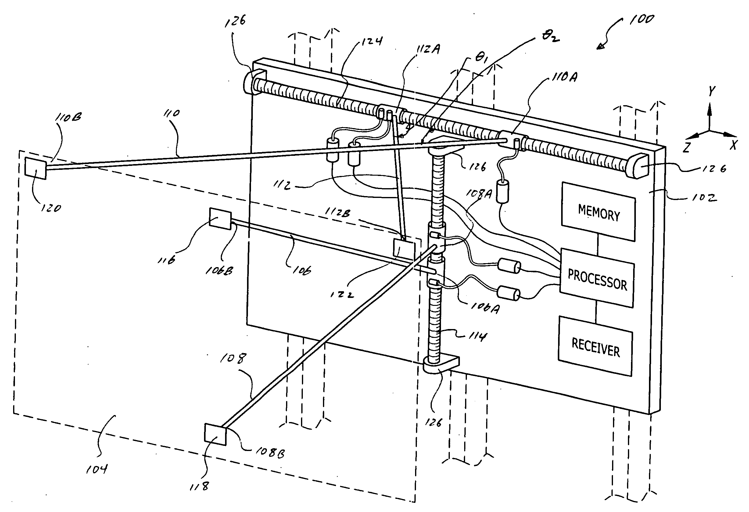
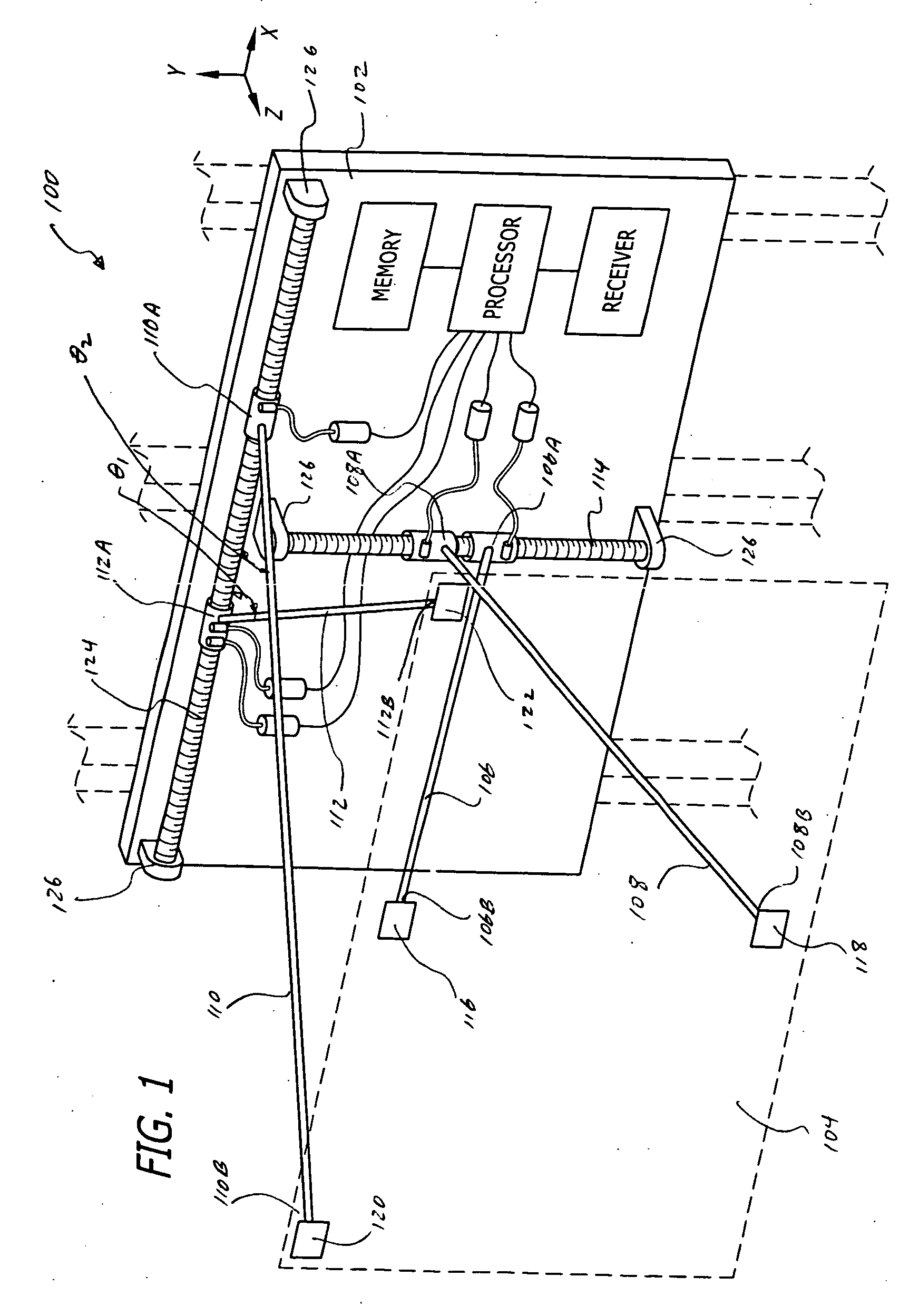
[0053]FIG. 1 shows a perspective view of a mounting system 100 capable of adjustably mounting a second mounting structure 104 to a first mounting structure 102 with reference to X, Y, and Z axes. In this example, the direction in the negative Y-axis may generally represent the gravitational force. The mounting system 100 may have a first set of beams 106 and 108, and a second set of beams 110 and 112. The beam 106 has a first end 106A and a second end 106B, where the first end 106A may slide along a guiding structure 114 juxtaposed to the first mounting structure 102 substantially in the Y-axis. The second end 106B of the beam 106 may be pivotally coupled to the second mounting structure 104 at a location 116 of the second mounting structure 104. The beam 108 has a first end 108A and a second end 108B, where the first end 108A may slide along the guiding structure 114. The second end 108B of the beam 108 may be pivotally coupled to the second mounting structure 104 at a location 118...


PUM


Abstract

A mounting system is capable of adjusting the viewing angle of a monitor. The mounting system includes at least two sets of beams between a first mounting structure and a second mounting structure. The first mounting structure may be adapted to attach to a wall, and the second mounting structure may be adapted to couple to a monitor such as a plasma or LCD television. Each of the two sets of beams may be coupled to a motor so that the two sets of beams may extend or retract independently to move the second mounting structure relative to the first mounting structure, thereby adjusting the viewing angle of the monitor. The mounting system may include a remote control to send control signals to tilt or move the monitor laterally. The remote control may have a preset button to remember a predetermined position of the monitor, so that activation of the preset button causes the mounting system to move the monitor to the predetermined position.

Description

RELATED APPLICATIONS [0001] This application claims priority to three provisional application Ser. Nos.: (1) 60 / 652,685 filed Feb. 14, 2005; (2) 60 / 663,819 filed Mar. 21, 2005; and (3) 60 / 667,715 filed Mar. 31, 2005, which are all incorporated by reference.FIELD OF THE INVENTION [0002] This invention is directed to a mounting system capable of adjusting the position of an apparatus relative to a reference plane. In particular, the mounting system is capable of mounting a monitor to a surface, such as a wall, and adjusting the viewing angle of the monitor either manually or based on an input signal from a remote control. BACKGROUND OF THE INVENTION [0003] Flat panel monitors such as computer monitors, TFT, LCD, plasma, slim televisions, and the like (collectively referred to as “monitor(s)”) are becoming popular because they can be mounted onto a wall to save floor space and for their aesthetically pleasing appearance. In particular, monitors are generally mounted to a wall with a me...

Claims


Application Information

Patent Timeline
IPC IPC(8): H04N5/645
CPCF16M11/18F16M11/10F16M13/02G06F1/1601
Inventor OH, SUNG I.
Owner CLO SYST
Why Eureka
Try Eureka