Automatic processing of aerial images

a technology of automatic image processing and aerial images, applied in the field can solve the problems of unfavorable human analyst work, high difficulty in achieving the effect of automatic image processing, and inability to achieve uniform scal

Active Publication Date: 2006-10-26
M A M D DIGITAL DATA PROCESSING SYST +1
View PDF3 Cites 99 Cited by
  • Summary
  • Abstract
  • Description
  • Claims
  • Application Information

AI Technical Summary

Benefits of technology

[0009] a three-dimensional image filter for comparing at least one of the first and second image pairs at the change candidates using three-dimensional image information in the image pairs to retain change candidates correlating with three-dimensional image information and to reject change candidates not correlating with three-dimensional image information, thereby to produce a refined list of change candidates.
[0100] classifying the identified tie points as stable or unstable tie points, thereby to eliminate unstable tie points and base the registration on stable tie points.

Problems solved by technology

Nevertheless the sheer volume of photographic images that can be available in a high precision survey means that even such methods leave a huge amount of work for a human analyst to have to carry out.
A high precision survey of a region may in fact photograph the region from a fairly low altitude with an ability to resolve objects of the ten-centimeter order of magnitude, and if a human analyst has to consider every suspect change that the computer locates then the effectiveness of the process is highly problematic.
A further issue is that the aerial photograph is taken from a certain position and a certain angular inclination.
It does not have a uniform scale.
Until the issue of scale is dealt with, it is difficult to begin the process of looking for changes since two images taken from even slightly differing positions simply do not show the same thing.
However, even after dealing with the issue of scale, current automatic image processing systems have difficulty in ruling out irrelevant differences between photographs such as those due to naturally moving objects, those due to lighting changes between the times the photographs were taken, those due to failure to carry out accurate matching between the successively taken photographs and the like.
However this does not always work since similar points which are not actually the same can erroneously be chosen.
Thus any kind of terrain in which repeating features appear is liable to erroneous matching of similar neighbors.

Method used


Image

  • Automatic processing of aerial images
  • Automatic processing of aerial images
  • Automatic processing of aerial images

Examples


Embodiment Construction

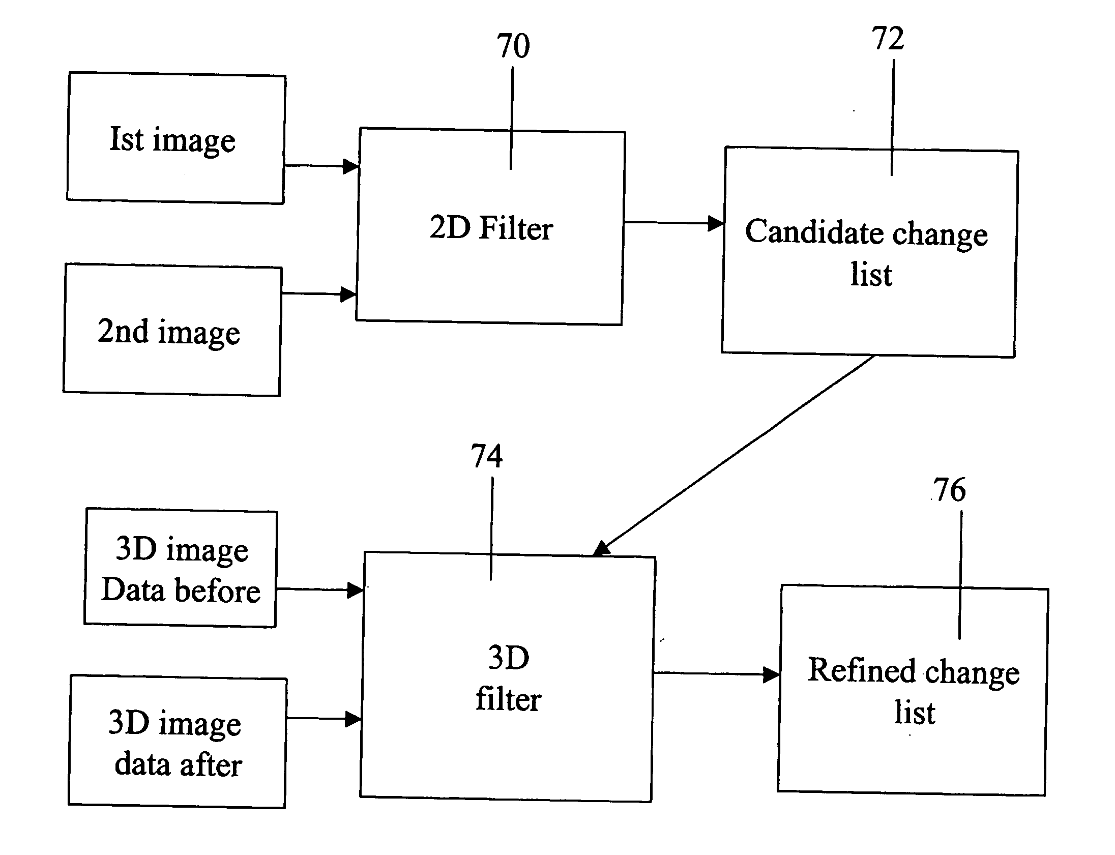
[0122] The present embodiments comprise a system for utilizing three dimensional data in stereoscopic images to confirm or eliminate changes apparent from the two-dimensional data of the same images. The system comprises improved methods of registration of images both in two dimensions and in three dimensions, and improved methods of removing bias to enable a reliable three-dimensional comparison to be made. Furthermore the preferred embodiments use an ordered system of filtering for changes which has the consequence of restricting the more processor-intensive parts of the comparison process to change candidates already filtered by less processor-intensive stages.

[0123] The principles and operation of a change detection system according to the present invention may be better understood with reference to the drawings and accompanying description.

[0124] Before explaining at least one embodiment of the invention in detail, it is to be understood that the invention is not limited in i...


PUM


Abstract

Change detection apparatus for detection of changes between first and second stereoscopic image pairs obtained at different times of a substantially similar view, comprises: a two-dimensional image filter for comparing first and second image pairs to obtain an initial list of change candidates from two-dimensional information in the image pairs, and a three-dimensional image filter for comparing the image pairs at locations of the change candidates using three-dimensional image information. The apparatus retains those change candidates correlating with three-dimensional image change and rejects change candidates not correlating with three-dimensional image change, and produces a refined list of change candidates.

Description

FIELD AND BACKGROUND OF THE INVENTION [0001] The present invention relates to a method and apparatus for processing of automatic images and, more particularly, but not exclusively to a method and apparatus that allows the automatic detection of changes from images taken of the same place at different times. [0002] In the early days of aerial photography, images had to be pored over painstakingly to find out required information, especially when what was needed was to spot small changes. Today the task has been made easier by the use of automatic image analysis techniques to find candidate differences which are then presented to a human user to make a final identification. Nevertheless the sheer volume of photographic images that can be available in a high precision survey means that even such methods leave a huge amount of work for a human analyst to have to carry out. A high precision survey of a region may in fact photograph the region from a fairly low altitude with an ability to...

Claims


Application Information

Patent Timeline
Patent Type & Authority Applications(United States)
IPC IPC(8): H04N13/00G06K9/00G06K9/36G02B27/22G06T5/50G06T7/20G06V20/13
CPCG06K9/0063G06T5/50G06T2207/10032G06T7/2086G06T2207/10021G06T7/2053G06T7/254G06T7/285G06V20/13G06T7/00
Inventor SHRAGAI, MEIRLIBERMAN, JOSEPH
Owner M A M D DIGITAL DATA PROCESSING SYST
Why Eureka
Try Eureka