Developing apparatus

a technology of developing apparatus and developing body, which is applied in the direction of electrographic process apparatus, instruments, optics, etc., can solve the problems of increasing the size of the apparatus, generating density unevenness, and density unevenness, and achieves the effects of small size, light weight and high image quality

Inactive Publication Date: 2006-10-26
PANASONIC CORP
View PDF3 Cites 83 Cited by
  • Summary
  • Abstract
  • Description
  • Claims
  • Application Information

AI Technical Summary

Benefits of technology

[0014] Therefore, with the foregoing in mind, it is an object of the present invention to solve at least the above-described problem in the prior art, and to provide a developing apparatus that can provide high image quality, a small size, a light weight and low costs, which can effectively prevent the generation of the ghost due to the poor detachment of the developer, after development. The present invention also provides a developing apparatus which prevents the generation of the unevenness in density between a left part and a right part of an image region due to lack of an adequate amount of the developer transported, and can circulate the developer smoothly, without using the drawing-up roller or the like having the magnet therein, even in a configuration where the detaching region of the developer in which the pair of magnets of the same polarity are disposed is positioned above the shaft center (the rotational center line) of the development roller, such as the narrow-pitch image forming system that utilizes the two-component developing system.

Problems solved by technology

This type of tandem type image forming apparatus includes image forming units for each of four colors that are disposed in parallel, and thus gives rise to a problem that the size of the apparatus increases.
In the two-component developing system, detaching the developer that is attached on the surface of the development roller after the development is important, and if the detachment of the developer, after development, is not sufficient, a toner density of the developer at a part where the toner is consumed and a toner density where the toner is not consumed are different, which may cause generation of unevenness of density, which is called a “ghost (or memory)” image.
However, in the narrow-pitch image forming system in which the development roller is positioned above the cleaning member of the upstream adjacently positioned photosensitive drum, since the cleaning member of the upstream adjacently positioned photosensitive drum is positioned below and close to the development roller, the detaching region of the developer, where the pair of magnets of the same polarity are disposed is inevitably positioned above the shaft center (the rotational center line) of the development roller.
As a result, the detachment of the developer using gravity cannot be achieved, which may cause generation of the unevenness in density which can give rise to the above-noted “ghost”.
Thus, a problem arises in that the developing apparatus is complicated in configuration and has a large size.
In addition, the magnet is required to be disposed in the drawing-up roller, which may increase manufacturing costs and a weight of the apparatus.

Method used


Image

  • Developing apparatus
  • Developing apparatus
  • Developing apparatus

Examples


embodiment 1

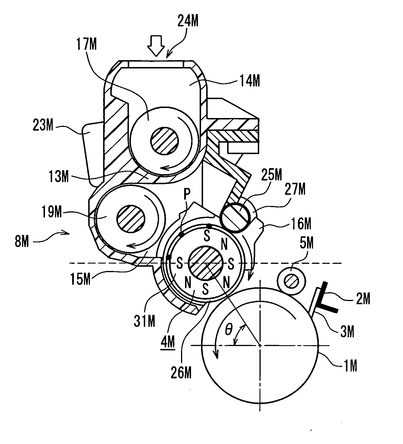
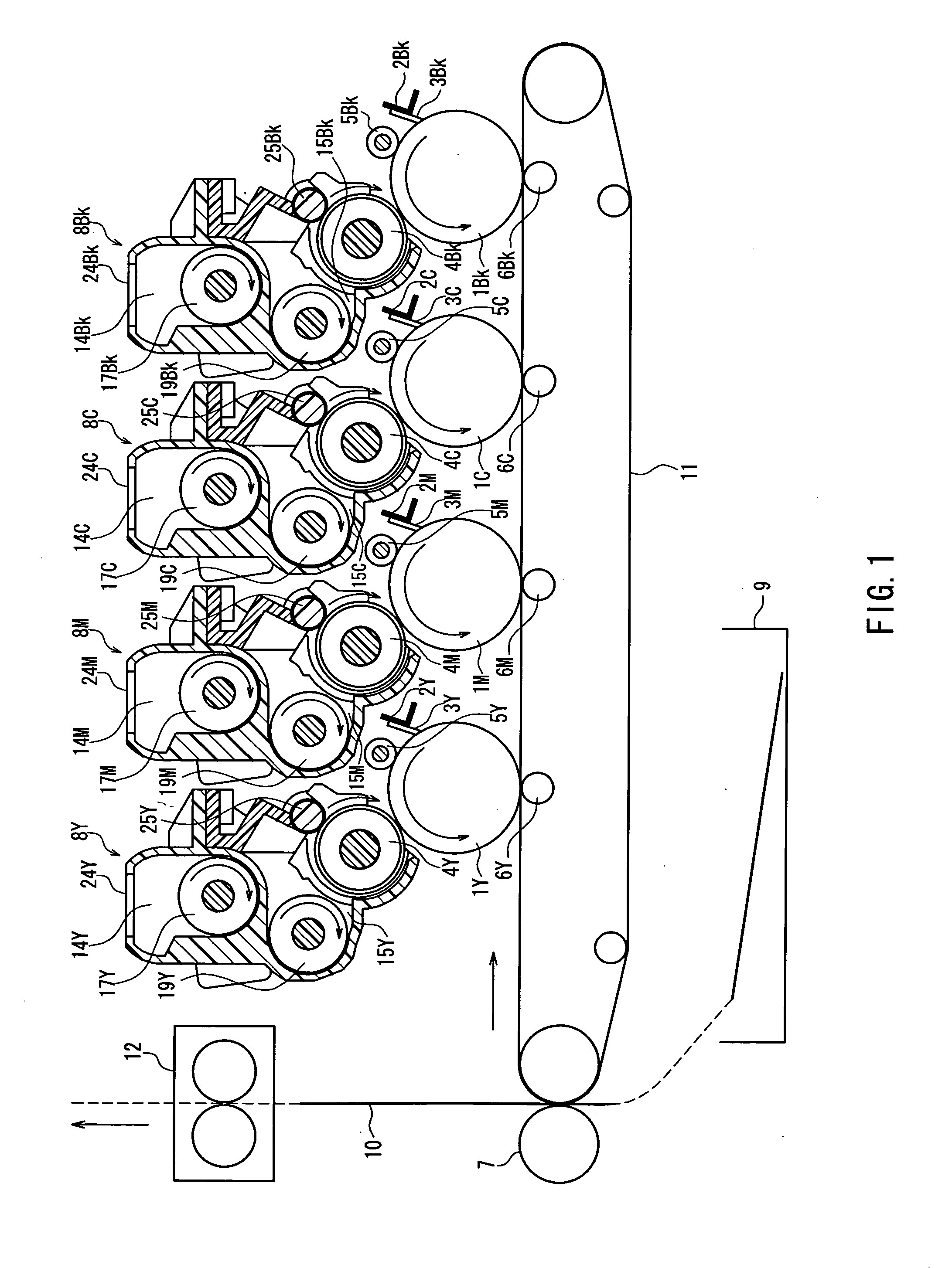
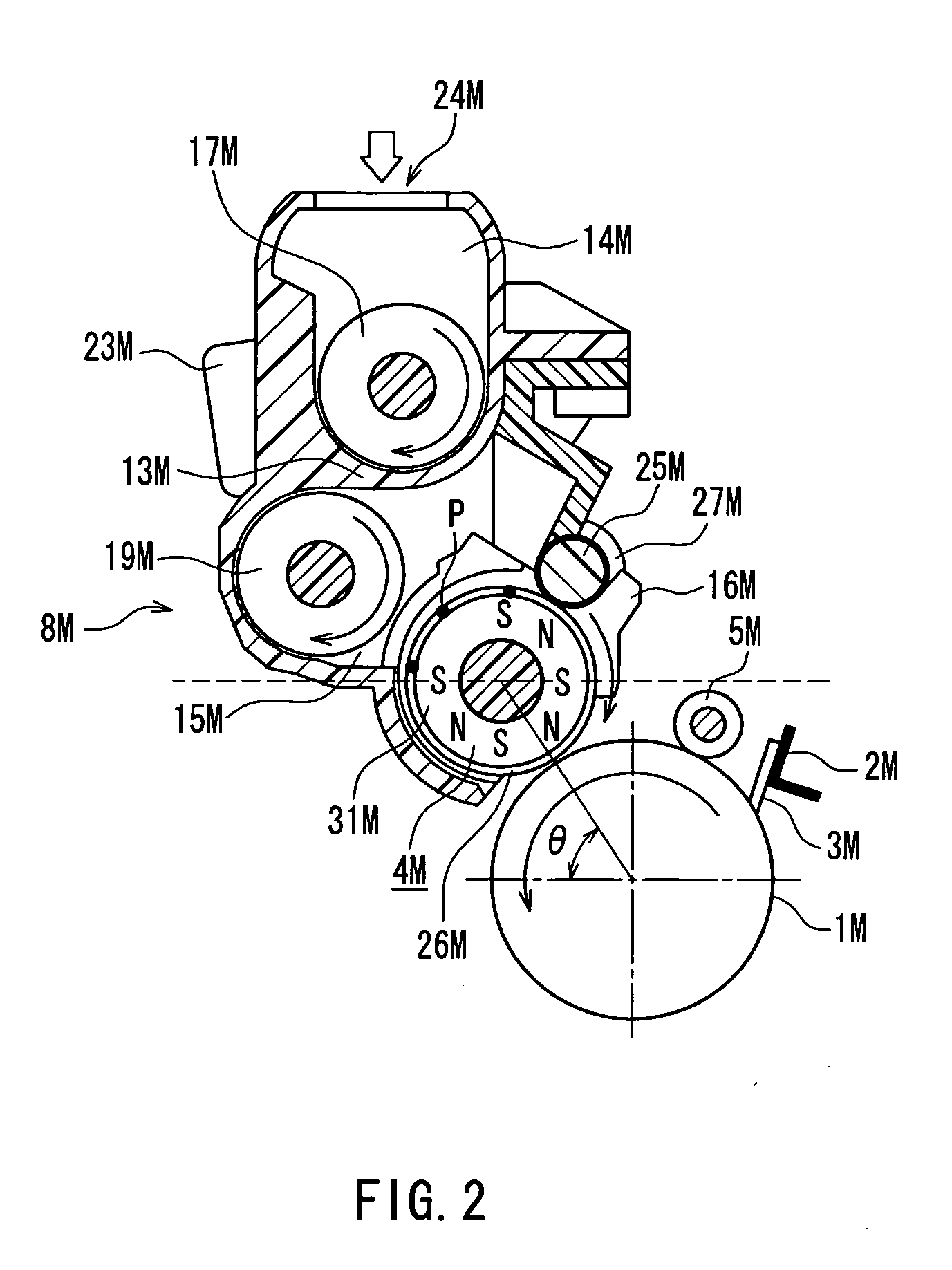
[0065]FIG. 1 is a cross-sectional view schematically showing a configuration of an entire image forming apparatus according to Embodiment 1 of the present invention, and FIG. 2 is a cross-sectional view schematically showing a relevant part of an image forming unit according to Embodiment of the present invention. FIG. 3 is an external perspective view showing a developing apparatus according to Embodiment 1 of the present invention, and FIG. 4 is a cross-sectional view showing a relevant part of the developing apparatus of FIG. 3, seen from the direction of arrow A. FIG. 5 is a cross-sectional view taken along line B-B of FIG. 4, FIG. 6A is an enlarged view showing a part C of FIG. 4, and FIG. 6B is a cross-sectional view taken along line D-D of FIG. 6A. FIG. 7 is a chart or a graph showing magnetic pole arrangement and a distribution of magnetic flux density in a development roller according to Embodiment 1 of the present invention. In FIG. 5, a photosensitive drum that is omitted...

embodiment 2

[0148] Developing apparatuses were manufactured by modifying the developing apparatus of Embodiment 1 so as to have a ratio of (mg0×l×v) / M0 fixed to be 0.025, and center distances d of 13.8 mm, 14.3 mm, 14.8 mm, 15.0 mm, 15.3 mm, 17.0 mm, 19.0 mm, 20.0 mm, 21.0 mm and 25.0 mm, respectively. Then, respective image density differences ΔIDg were measured. FIG. 10 shows the results. As shown in FIG. 10, it is found that, when the center distance d was not more than 2r+R (r=6 mm, R=7 mm, and thus, 2r+R=19 mm), the image density difference ΔIDg was not more than 0.025, and thus the ghost was also improved.

[0149] Moreover, by using plural developing apparatuses that were manufactured similarly to the above, unevenness (i.e., variation) a of the image density on a whole solid image was evaluated. The evaluation of the unevenness a of the image density on the whole solid image was performed by measuring a standard deviation of image densities ID at plural measurement points, after printing ...

embodiment 3

[0152] Evaluation of the ghost was performed by varying the volume resistivity of the carrier of Embodiment 1 in the electric field of 2 kV / cm to five levels of 1×10⁶ Ω·cm, 1×10⁸ Ω·cm, 1×10¹⁰ Ω·cm, 1×10¹² Ω·cm, 1×10¹⁴ Ω·cm and 1×10¹⁶ Ω·cm. That is, the image density differences ΔIDg were measured, while varying the volume resistivity of the carrier in the electric field of 2 kV / cm. FIG. 12 shows the results. As shown in FIG. 12, it is found that, when the volume resistivity of the carrier was not more than 1×10¹⁰ Ω·cm, the image density difference ΔIDg was not more than 0.01, and thus the ghost was further improved. It is also found that, in the measurement with a reflection densitometer RD914 manufactured by Macbeth, the image density difference ΔIDg was substantially zero, and a uniform image could be obtained. This is thought to be because, since electric charge generated by frictional charging with the toner was not accumulated in the carrier, an image force of the carrier appli...


PUM


Abstract

The present invention provides a developing apparatus that can effectively prevent generation of a ghost due to poor detachment of a developer after development, and generation of unevenness in density between a left part and a right part of an image region due to lack of an amount of the developer transported. The developing apparatus satisfies the relationship r+R≦d≦3r+R where r denotes a rotational radius of a second developer transporting screw, R denotes a rotational radius of a development roller, and d denotes a center distance between the second developer transporting screw and the development roller. The developing apparatus also satisfies the relationship M0≧(mg0×v×l) / 0.02 where mg0 (g / mm2) denotes an amount of a toner per unit area that is supplied from the development roller to an electrostatic latent image having 100% image coverage which is formed on a photosensitive drum, v (mm / s) denotes a rotational peripheral velocity of the photosensitive drum, l (mm) denotes a maximum printing width on the photosensitive drum, and M0 (g / s) denotes an amount of the developer transported per unit time by the second developer transporting screw in a second developer transport direction.

Description

CROSS-REFERENCE TO RELATED APPLICATIONS [0001] The present disclosure relates to subject matter contained in priority Japanese Application No. 2005-127437, filed on Apr. 26, 2005, which is herein expressly incorporated by reference in its entirety. BACKGROUND OF THE INVENTION [0002] 1. Field of the Invention [0003] The present invention relates to a developing apparatus used for developing an electrostatic latent image that is formed on an electrostatic latent image bearing member in an image forming apparatus such as a copier, a printer, a facsimile and the like. [0004] 2. Description of Related Art [0005] Conventionally, an electrophotographic image forming apparatus, which optically scans an original image portion that is supported on an outer circumferential surface of a uniformly electrified photosensitive drum (an electrostatic latent image bearing member) so as to form an electrostatic latent image, and converts the electrostatic latent image into a visible image by using a t...

Claims


Application Information

Patent Timeline
Patent Type & Authority Applications(United States)
IPC IPC(8): G03G15/09
CPCG03G15/09G03G15/0868G03G15/0891
Inventor OKUDA, AKINOBUHAYASHI, KAZUMASATOYODA, AKINORIOOTSUKA, MASAOYASUDA, HIDEKITAKAHASHI, NAOKI
Owner PANASONIC CORP
Why Eureka
Try Eureka