Rotation positioning device for a coil of a magnetic resonance imaging apparatus

a magnetic resonance imaging and positioning device technology, applied in the field of rotation positioning devices for the coils of the magnetic resonance imaging apparatus, can solve the problems that the mri apparatus employing such a head coil cannot meet such a requirement, cannot solve, and cannot move, and achieve the effect of precise positioning of the body part and free rotation

Inactive Publication Date: 2006-10-26
SIEMENS AG
View PDF7 Cites 25 Cited by
  • Summary
  • Abstract
  • Description
  • Claims
  • Application Information

AI Technical Summary

Benefits of technology

[0019] The first driving member and the second driving member can respectively select a proper transmission mode, such as a rack and a gear. The first rotating member and the second rotating member can be a sliding recess and a guiding rail or a sliding pin and a guiding recess, respectively, wherein the sliding recess can be fit over the guiding rail and slide along it, or alternatively the sliding pin can be inserted in the guiding recess and slide along it. The second driving member can be driven manually or by an external driving source connected thereto to drive the first driving member, thereby driving the backing member to rotate through the cooperation of the first rotating member and the second rotating member. Also, by appropriate configuration of parameters, such as position and size, of the first driving member and the second driving member, the rotation angle or range of the backing member can be controlled precisely and quantitatively.
[0020] The rotation positioning device for the coil of the MRI apparatus according to the present invention achieves free rotation and precise positioning of the body part to be examined, thus solving the problem that of the body part to be examined, once fixed by a bearing bracket, a soft mat, an air bag or a vacuum bag within the accommodating cavity, cannot move quantitatively in any direction, and meeting the requirement that when the coil of the MRI apparatus needs to perform an examination with the body part to be examined in other particular positions, such as the position of the body part after it rotates through a particular angle.

Problems solved by technology

Although, as described above, MRI is capable of producing an image in an arbitrary direction directly, the direct production of an image in an arbitrary direction is limited to only some fixed positions, thus an MRI apparatus employing such a head coil has certain disadvantages.
Moreover, even though the body part to be examined can be adjusted properly in terms of position in the direction perpendicular to the accommodating cavity, when the examination needs to produce an image with the body part to be examined in other particular position, such as the position of the body part after it rotates through a particular angle, an MRI apparatus that employs such a head coil cannot meet such a requirement.
However, MRI apparatus of this type still does not solve the problem that the body part to be examined of the patient after being fixed, cannot move.

Method used


Image

  • Rotation positioning device for a coil of a magnetic resonance imaging apparatus
  • Rotation positioning device for a coil of a magnetic resonance imaging apparatus
  • Rotation positioning device for a coil of a magnetic resonance imaging apparatus

Examples


Embodiment Construction

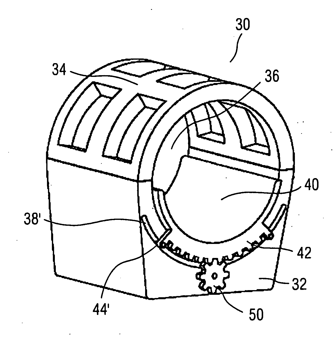
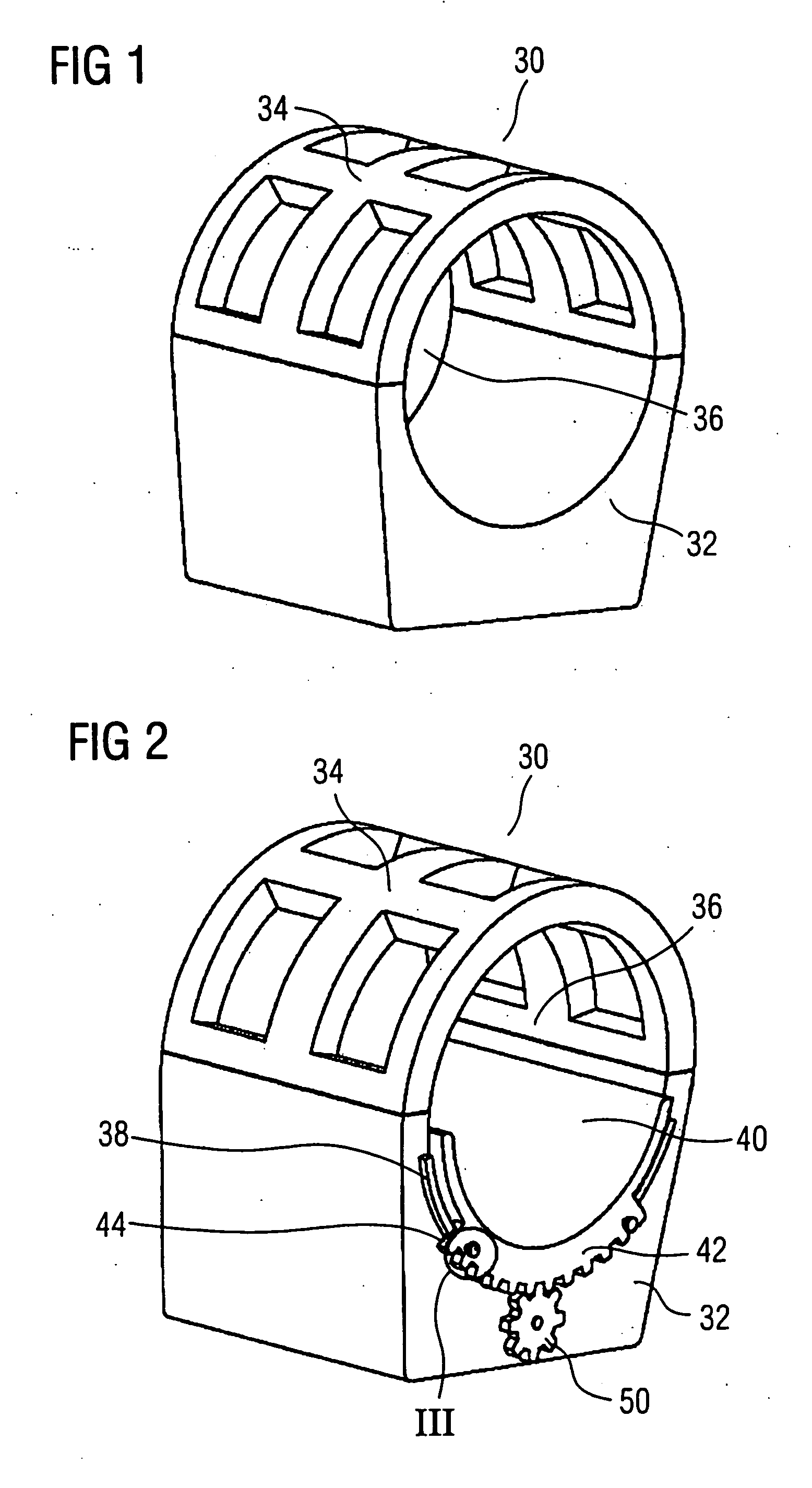
[0029] A rotation positioning device according to the present invention is provided on a coil of an MRI apparatus, for allowing free rotation and precise positioning of a body part to be examined. The present invention can be widely applied to various coils of the MRI apparatus. Although only one example in which the present invention is applied to a head coil is discussed in the preferred embodiment and succeeding embodiments, the present invention is not limited to this. As will be understood by those skilled in the art, devices applied to other coils that are identical with or similar to the rotation positioning device for the coil of the MRI apparatus according to the present invention fall within the scope of the present invention.

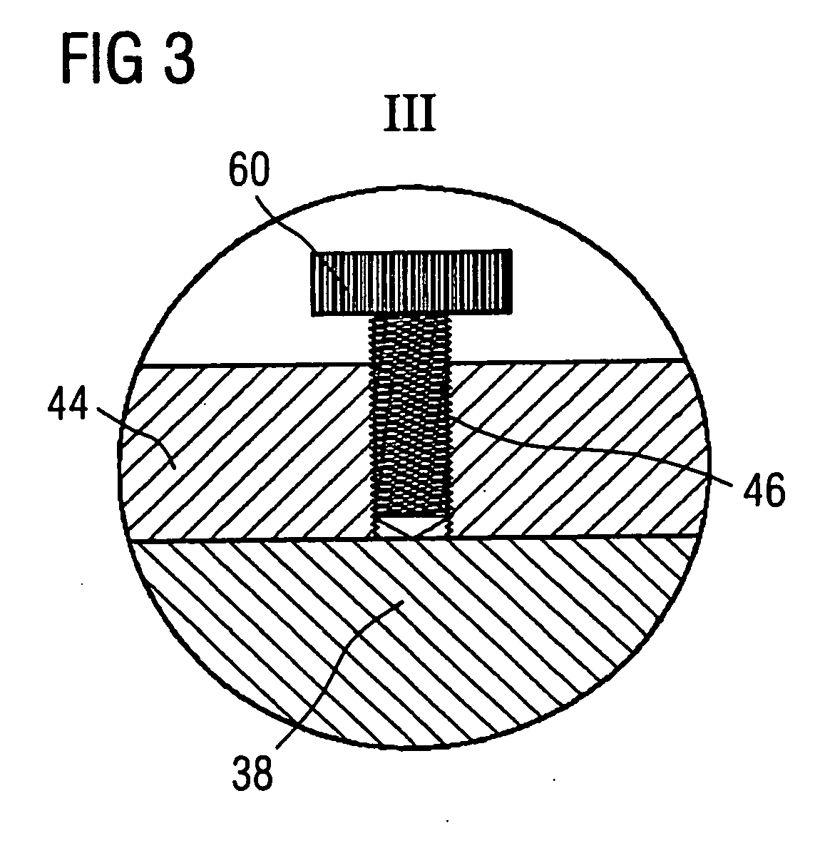
[0030] Referring to FIG. 2, a head coil 30 has a base 32 and a top 34 that is fixed on top of the base 32. It is understood that the base 32 and the top 34 may also be integrated with each other. An upper surface of the base 32 defines a concave semi...


PUM


Abstract

A rotation positioning device for a coil of a magnetic resonance imaging apparatus, having a cavity in the coil for accommodating a part to be examined, has a backing member that can freely rotate within this accommodating cavity. The backing member is provided with a first driving member and a first rotating member, and the coil is provided with a second driving member and a second rotating member. The first driving member and the second driving member form a transmission pair, and the first rotating member can rotate relative to the second rotating member under the drive of the first driving member and the second driving member. The second driving member can be driven manually or by an external driving source connected thereto to drive the first driving member, thereby driving the backing member to rotate via the cooperation of the first rotating member and the second rotating member. Also, by appropriate configuration of parameters, such as position and size, of the first driving member and the second driving member, the rotation angle or range of the backing member can be controlled precisely and quantitatively.

Description

BACKGROUND OF THE INVENTION [0001] 1. Field of the Invention [0002] The present invention relates to a positioning device for a coil of a magnetic resonance imaging (MRI) apparatus, and more particularly to a rotation positioning device for a coil of an MRI apparatus. [0003] 2. Description of the Prior Art [0004] In recent years, MRI has become an important tool in diagnostic medicine. MRI employs radio frequency (RF) energy as a stimulus, to observe a magnetic resonance signal emitted by atomic nuclei of a specific type during the process from being perturbed to regaining equilibrium under the effect of a strong static magnetic field. The magnetic resonance signal is converted to an electrical signal using Faraday's law, and an image of the atomic density in an object is calculated via a two dimensional Fourier transform. [0005] Using MRI to perform an examination has the following advantages: [0006] i) among current means of medical imaging, MRI has the highest contrast resolution...

Claims


Application Information

Patent Timeline
Patent Type & Authority Applications(United States)
IPC IPC(8): A61B5/05
CPCG01R33/34046A61B5/0555A61B5/055
Inventor LIU, KE CHENGXUE, TING QIANGWANG, JIAN
Owner SIEMENS AG
Why Eureka
Try Eureka