Method and apparatus for a multi-modality imaging system

Active Publication Date: 2006-10-26
GENERAL ELECTRIC CO
View PDF33 Cites 28 Cited by
  • Summary
  • Abstract
  • Description
  • Claims
  • Application Information

AI Technical Summary

Problems solved by technology

A misalignment of the coordinate systems may directly result in a misregistration of the images.
Misregistration results not only in inaccurate localization, but also to incorrect attenuation correction of the functional image.
However, a patient table and table support may not be able to accommodate the alignment requirements while supporting a patient cantilevered out from the table support during an examination due to the extreme length of travel the patient table must travel to reach both imaging assemblies.
For

Method used


Image

  • Method and apparatus for a multi-modality imaging system
  • Method and apparatus for a multi-modality imaging system
  • Method and apparatus for a multi-modality imaging system

Examples


Embodiment Construction

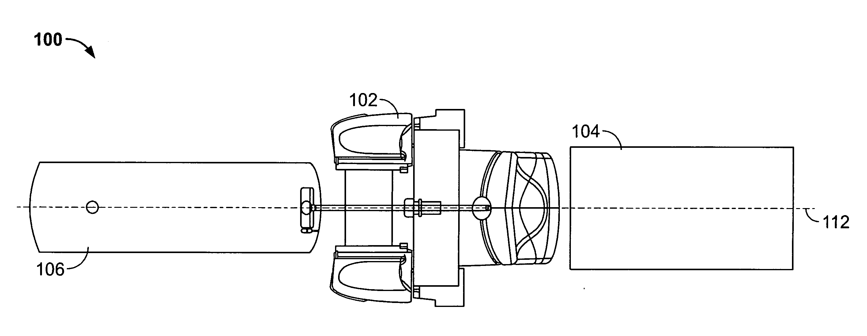
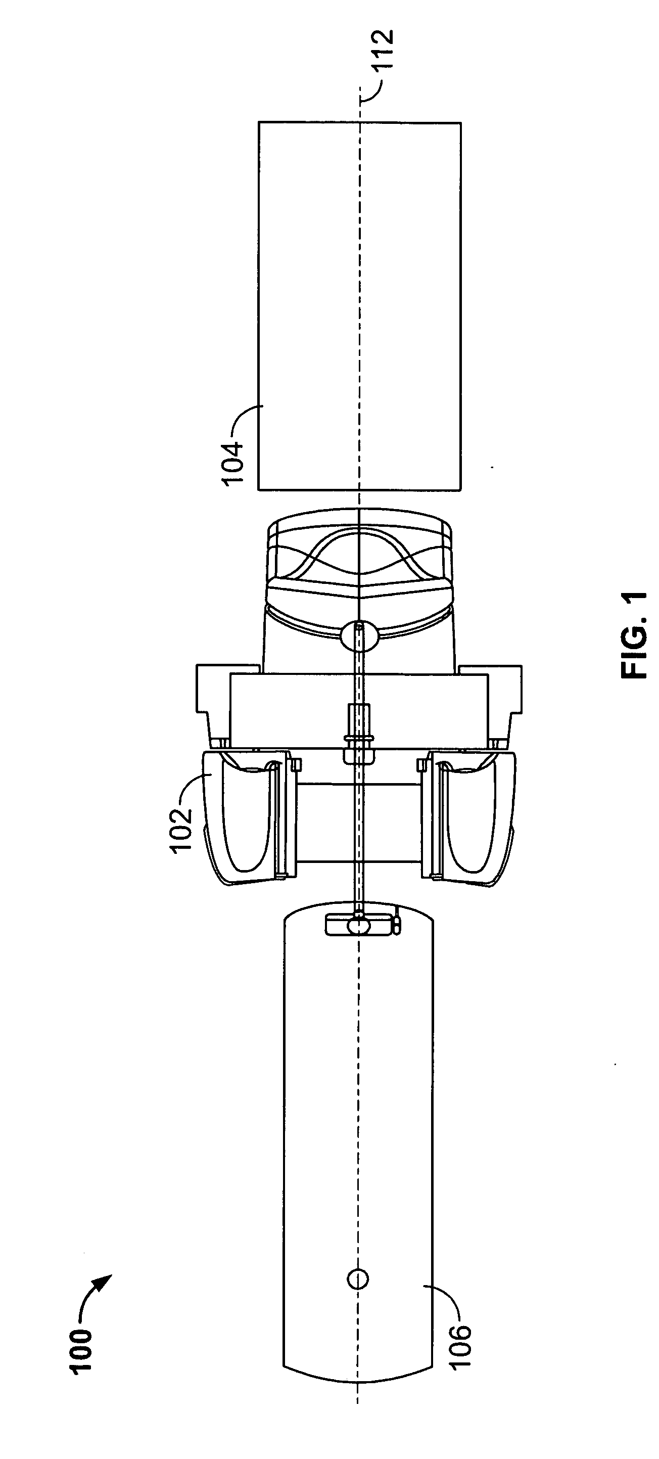
[0015]FIG. 1 is a schematic illustration of an exemplary embodiment of an imaging system 100. Imaging system 100 includes a first imaging assembly 102, a second imaging assembly 104, a patient table assembly 106, and a support mechanism (not shown). In the exemplary embodiment, imaging assembly 102 includes an associated examination axis 112, which defines the imaging axis of the first and the second imaging systems. As used herein, the examination axis is referenced to a single axis used to image the patient in both imaging systems. Each of imaging assemblies 102 and 104 may be, for example, any combination of a SPECT imaging assembly, a PET imaging assembly, a MRI imaging assembly, a CT imaging assembly, a Static X-Ray imaging assembly, a Dynamic (Fluoroscopy) X-Ray imaging assembly, a NM imaging assembly, and an ultrasound imaging assembly. Imaging assemblies 102 and 104 are aligned along the same examination axis 112.

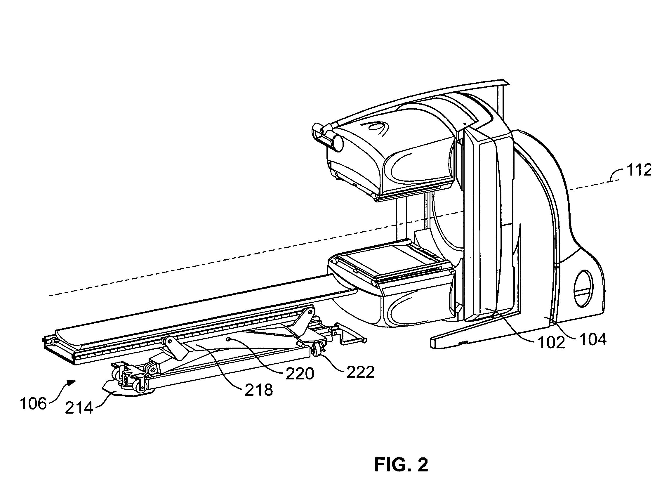
[0016]FIG. 2 illustrates an exemplary embodiment of patient t...


PUM


Abstract

An apparatus for examining a patient is provided. The apparatus includes a top plate, at least one top rail slideably coupled to said top plate, said top plate selectively positionable between a first imaging position and a second imaging position along an examination axis, a support member coupled to said at least one top rail, said support member configured to selectively change a position of said top plate along an axis perpendicular to said examination axis, said support member comprises at least one guide pin slideably coupled to said at least one rail during movement of said support member,.said guide pin configured to retain said support member to said at least one top rail when said top rail is moved between a first modality position and a second modality position.

Description

BACKGROUND OF THE INVENTION [0001] This invention relates generally to imaging and treatment systems, and more particularly to methods and apparatus for aligning an object being scanned in multi-modality systems. [0002] At least some multi-modality imaging and treatment systems are capable of using a combination of different modalities, such as, for example, Positron Emission Tomography (PET), Single Positron emission tomography (SPECT), Ultrasound, Magnetic Resonance Imaging (MRI), Computed Tomography (CT), Static X-Ray imaging, Dynamic (Fluoroscopy) X-Ray imaging, and radio-therapy. In a multi-modality system (sometimes referred to as a multi-modal system), a portion of the imaging hardware is utilized to perform different scans or treatments, (e.g., an image produced by SPECT is processed and displayed respectively, by the same computer and display, as an image produced by CT). However, the data acquisition systems (also referred to as an “imaging assembly”) may be different. For...

Claims


Application Information

Patent Timeline
IPC IPC(8): A61B5/05
CPCA61B6/032A61B6/037A61B6/0407A61B6/0457A61B6/4417A61B8/00A61B8/40A61B8/4416A61B6/5276A61B6/0487
Inventor YAKUBOVSKY, LEONIDVAISBURD, ALEXANDERHEFETZ, YARON
Owner GENERAL ELECTRIC CO
Why Eureka
Try Eureka