Stretch resistant therapeutic device

a therapeutic device and strain-resistant technology, applied in the field of strain-resistant therapeutic devices, can solve the problems of coils no longer being pushed, moved or replaced, etc., and achieve the effect of improving safety during coil retraction

Inactive Publication Date: 2006-10-26
MICRUS CORP
View PDF17 Cites 14 Cited by
  • Summary
  • Abstract
  • Description
  • Claims
  • Application Information

AI Technical Summary

Benefits of technology

[0007] Briefly, and in general terms, the present invention provides for a stretch resistant therapeutic device for release and deployment within a patient's vasculature, and an apparatus for release and deployment of the stretch resistant therapeutic device within a patient's vasculature, in which the therapeutic device is a vasoocclusive coil reinforced with an inner stretch resistant member to provide stretch resistance to the coil. The incorporation of an inner stretch resistant member may also allow the coil to be pushed even when such a coil is partially deployed, to improve safety during retraction of the coil. The vasoocclusive coil may be coated with one or more therapeutic agents, which may include a hydrogel. The vasoocclusive coil is reinforced by an inner stretch resistant member that is fixedly attached at one end at or near a distal end of the vasoocclusive coil, and that is detachably mounted at the other end of the vasoocclusive coil to an elongated pusher member to allow for placement and release of the vasoocclusive coil within the patient's vasculature.
[0008] Attachment of the inner stretch resistant member toward or at the distal end of the vasoocclusive coil without connection of the inner stretch resistant member to the other end of the vasoocclusive coil minimizes the increase of stiffness caused by reinforcement of the coil after the coil is released for deployment. An additional advantage is that the coil is free floating on the proximal end over the inner stretch resistant member. The inner stretch resistant member can be used to enhance radiopacity, aid in secondary shape configurations, and can be configured to aid desired stiffness of the coil, and can allow a softer coil to be used without stretching of the coil.

Problems solved by technology

Vasoocclusive coils made of platinum, gold, and other ductile materials will easily deform from their coil shape under tension, causing a potentially dangerous situation when the coil is partially in an aneurysm and partially stretched in the delivery catheter.
If it is determined that the coil is improperly placed, or is too large, the coil will need to be moved or replaced.
However, at this stage of the procedure, the coil can no longer be pushed, and must be slowly retracted out of the catheter as a wire.

Method used


Image

  • Stretch resistant therapeutic device
  • Stretch resistant therapeutic device
  • Stretch resistant therapeutic device

Examples


Embodiment Construction

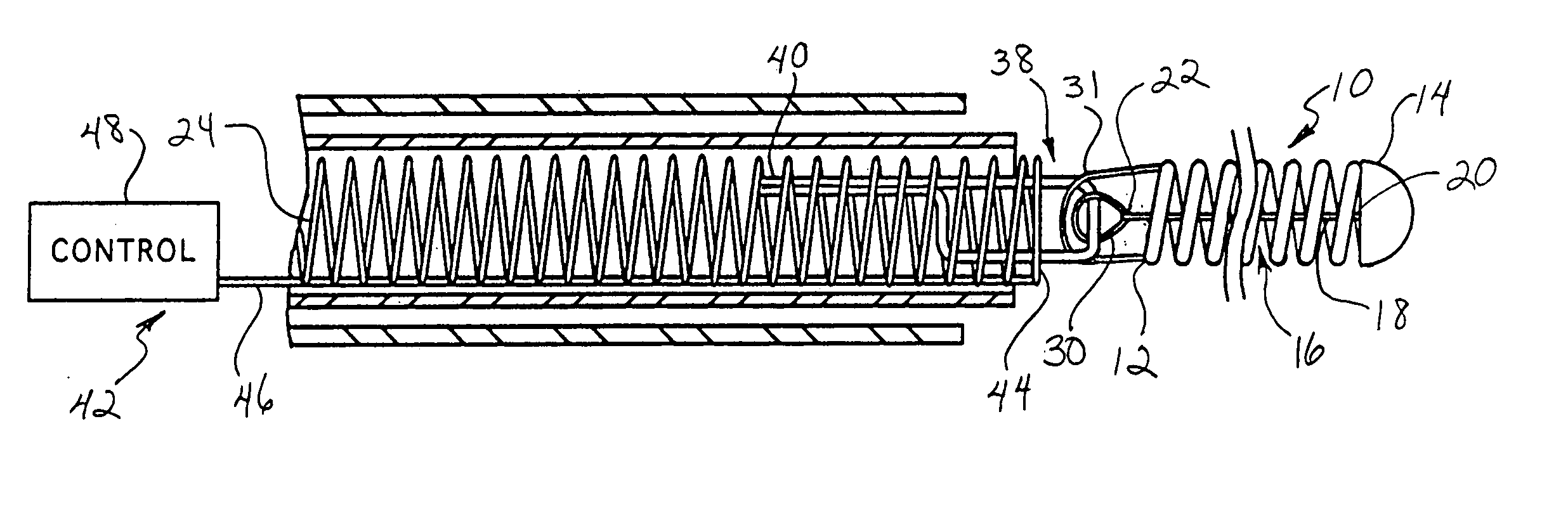
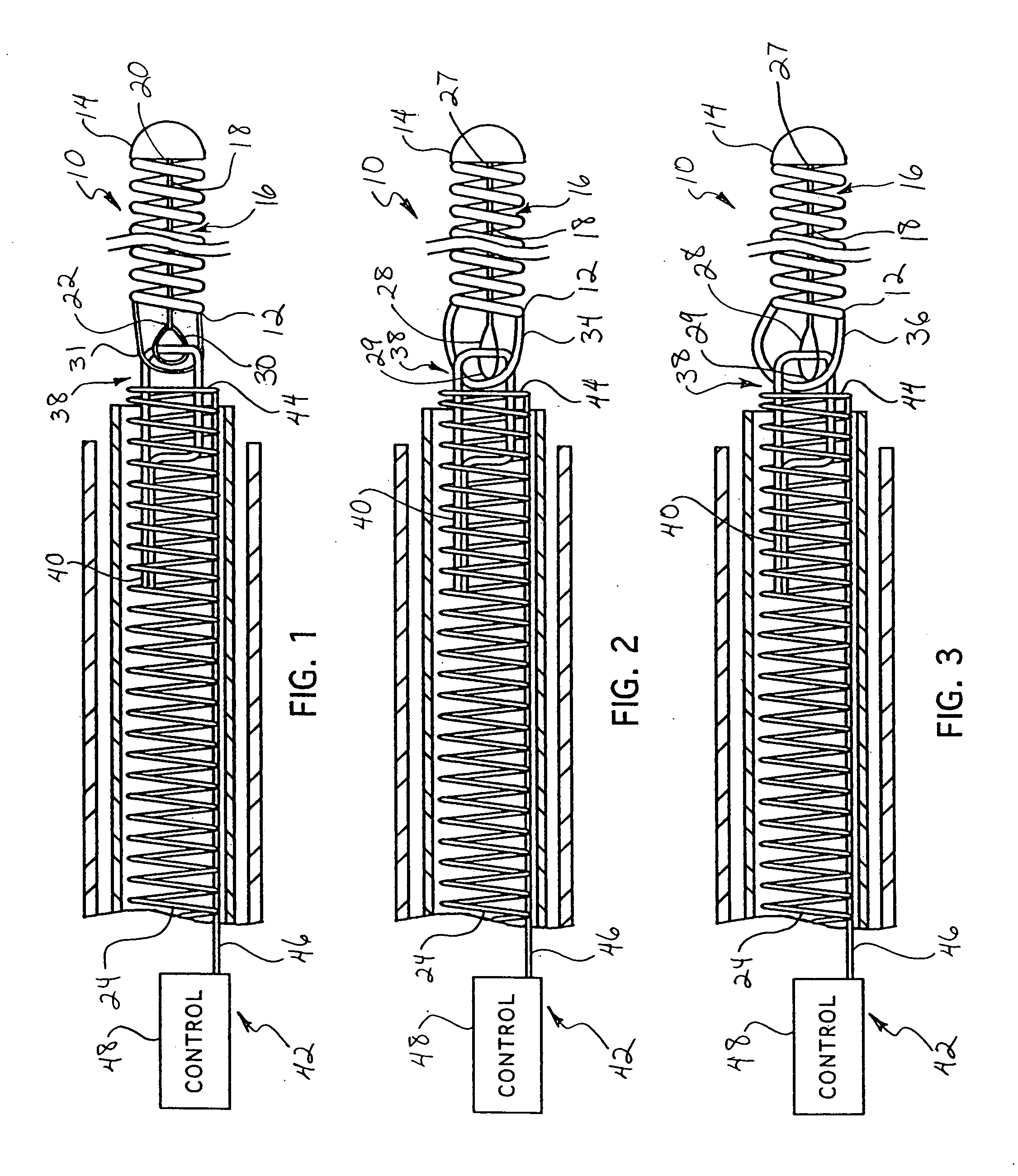
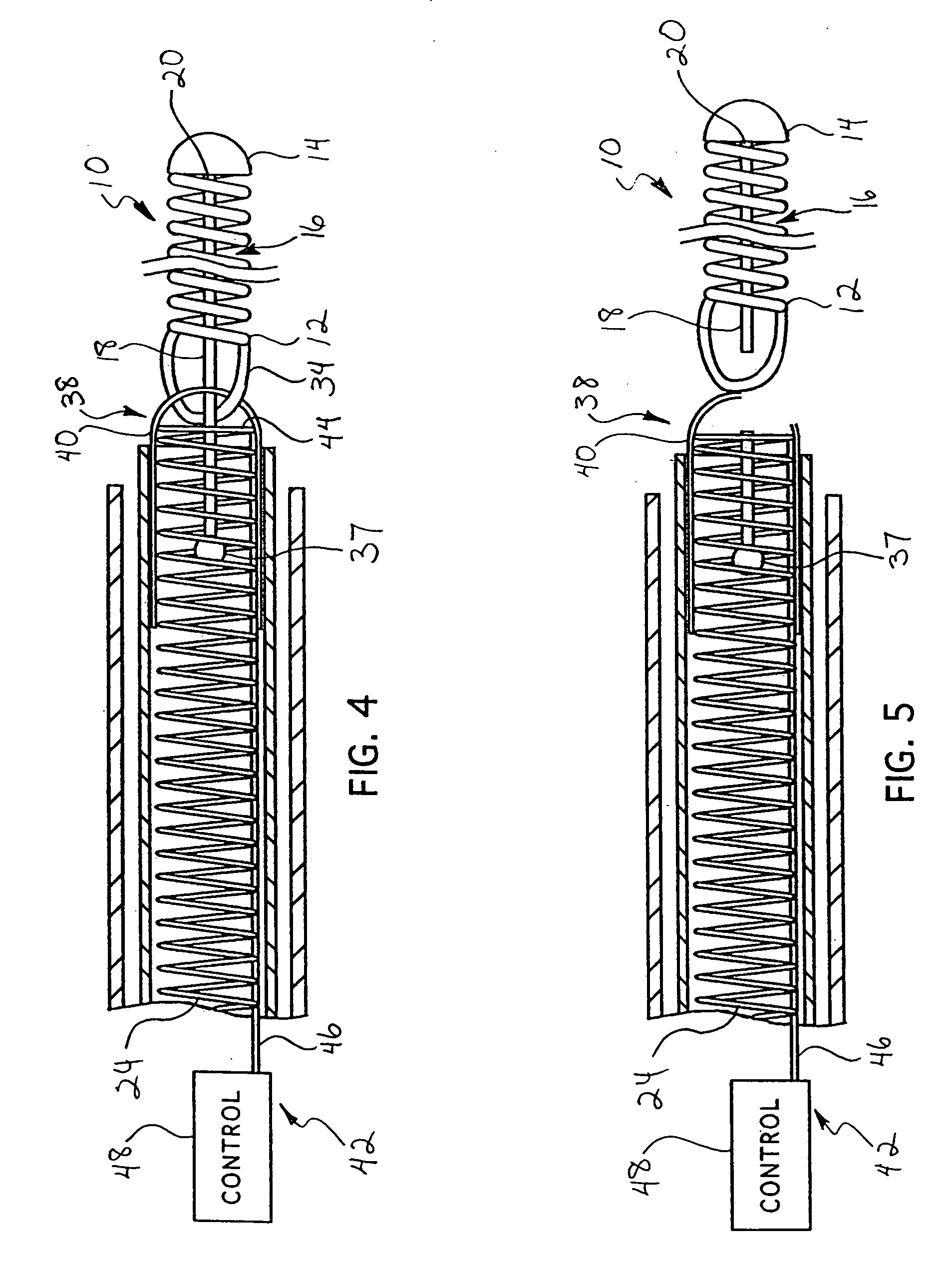
[0023] While the deployment of therapeutic devices has typically been accomplished by using a pusher member to push such a coil through a catheter, and a variety of detachment mechanisms to release the device from a pusher have been used, such coils are typically made of ductile materials that easily deform from their coil shape once released or partially released from the delivery catheter, so that the coils can no longer be pushed, and withdrawing of the coils back through the catheter can result in breakage of the coils. The present invention provides stretch resistance to such therapeutic devices to reduce the risk of the coils breaking during withdrawal of a coil for relocation or replacement. The present invention also minimizes the increase of stiffness caused by reinforcement of the coils when the coils are deployed so that the coils can freely transform to a desired secondary shape and conform to the dimensions of the target area.

[0024] As is illustrated in the drawings, t...


PUM

PropertyMeasurementUnit
shapeaaaaaaaaaa
electrical resistanceaaaaaaaaaa
thermoplasticaaaaaaaaaa

Abstract

A vasoocclusive coil is reinforced with a stretch resistant member to improve safety during retraction of the coil. The stretch resistant member is fixedly attached at one end to the vasoocclusive coil, and the other end of the stretch resistant member is detachably mounted to an elongated pusher member to allow for placement and release of the vasoocclusive coil within the patient's vasculature.

Description

BACKGROUND OF THE INVENTION [0001] This invention relates generally to implantable devices for interventional therapeutic treatment or vascular surgery, and more particularly concerns a stretch resistant therapeutic device such as an embolic or vasoocclusive coil and an apparatus for release and deployment of the stretch resistant therapeutic device within a patient's vasculature. [0002] The art and science of interventional therapy and surgery has continually progressed towards treatment of internal defects and diseases by use of ever smaller incisions or access through the vasculature or body openings, in order to reduce the trauma to tissue surrounding the treatment site. One important aspect of such treatments involves the use of catheters to place therapeutic devices at a treatment site by access through the vasculature. Examples of such procedures include transluminal angioplasty, placement of stents to reinforce the walls of a blood vessel or the like, and the use of vasooccl...

Claims


Application Information

Patent Timeline
Patent Type & Authority Applications(United States)
IPC IPC(8): A61M29/00A61BA61B17/12A61L31/00
CPCA61B17/12022A61B2017/12054A61B2017/00017A61B17/1219A61B17/12186A61B17/12154A61B17/1215A61B17/12145A61B17/1214A61B17/12113A61B17/12109A61B17/12099A61B2017/12068A61B17/32056A61B2017/00955A61B2017/00867A61B17/12A61M25/01A61F2/88
Inventor WILSON, PETERLEOPOLD, ERICDESAI, RUPESH K.
Owner MICRUS CORP
Why Eureka
Try Eureka