Method and apparatus for approximating gains in dynamic and steady-state processes for prediction, control, and optimization

a dynamic and steady-state process and approximation method technology, applied in adaptive control, process and machine control, instruments, etc., can solve problems such as insufficient non-linear information in dynamic data sets, inability to account for perturbations, and inability to adequately model system gain for existing steady-state operating conditions

Inactive Publication Date: 2006-10-26
ROCKWELL AUTOMATION TECH
View PDF47 Cites 24 Cited by
  • Summary
  • Abstract
  • Description
  • Claims
  • Application Information

AI Technical Summary

Problems solved by technology

These measurements do not account for the perturbations that exist when changing from one steady-state condition to another steady-state condition.
Unfortunately, almost always the dynamic gain k does not equal the steady-state gain K, since the steady-state gain is modeled on a much larger set of data, whereas the dynamic gain is defined around a set of operating conditions wherein an existing set of operating conditions are mildly perturbed.
This results in a shortage of sufficient non-linear information in the dynamic data set in which non-linear information is contained within the static model.
Therefore, the gain of the system may not be adequately modeled for an existing set of steady-state operating conditions.
Thus, when considering two independent models, one for the steady-state model and one for the dynamic model, there is a mis-match between the gains of the two models when used for prediction, control and optimization.
Also, the data utilized to parameterize the dynamic model do not represent the complete operating range of the process, i.e., the dynamic data is only valid in a narrow region.
These two models are not independent and are relatively complex to create.

Method used


Image

  • Method and apparatus for approximating gains in dynamic and steady-state processes for prediction, control, and optimization
  • Method and apparatus for approximating gains in dynamic and steady-state processes for prediction, control, and optimization
  • Method and apparatus for approximating gains in dynamic and steady-state processes for prediction, control, and optimization

Examples


Embodiment Construction

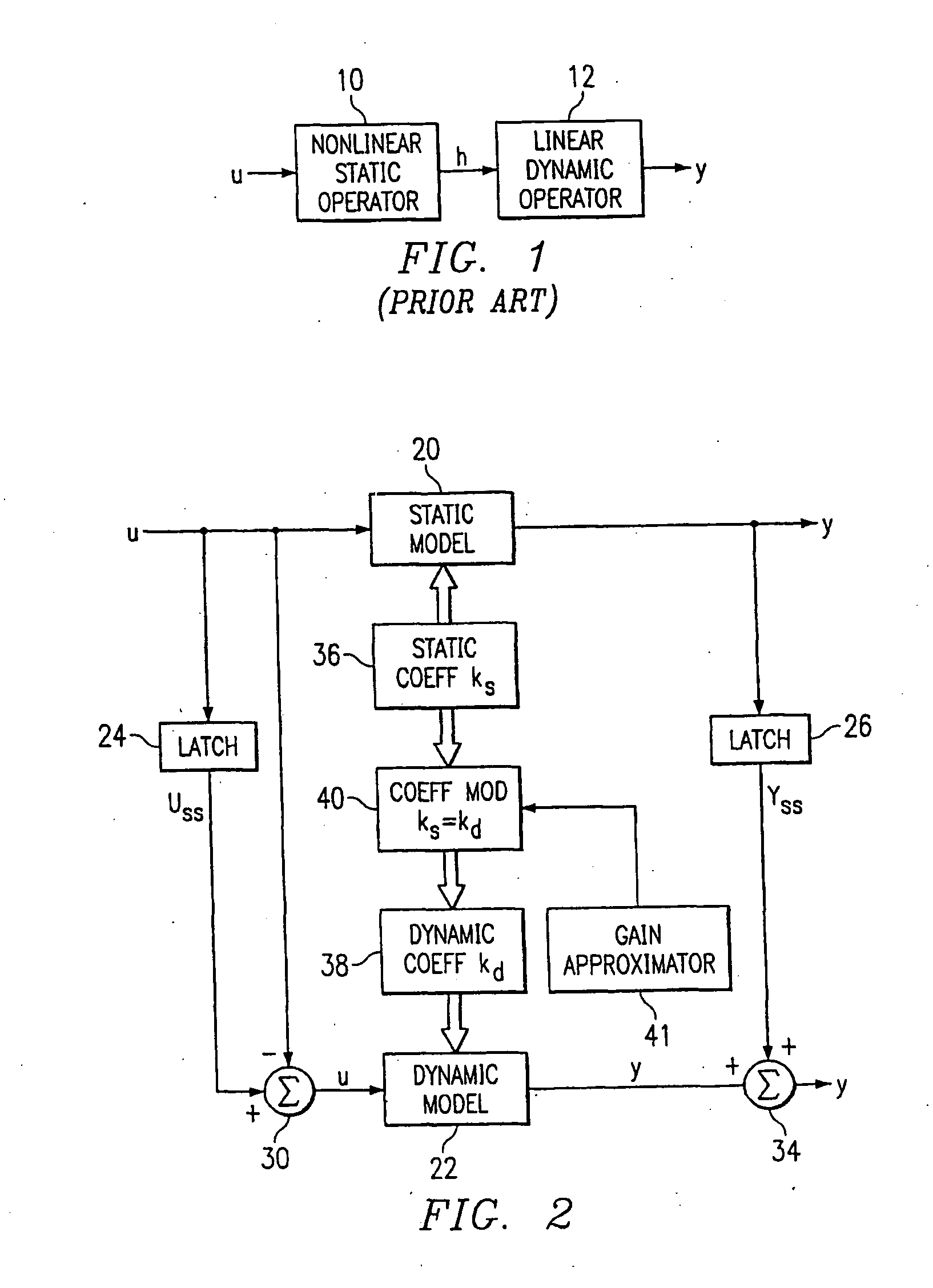
[0043] Referring now to FIG. 1, there is illustrated a diagrammatic view of a Hammerstein model of the prior art. This is comprised of a non-linear static operator model 10 and a linear dynamic model 12, both disposed in a series configuration. The operation of this model is described in H. T. Su, and T. J. McAvoy, “Integration of Multilayer Perceptron Networks and Linear Dynamic Models: A Hammerstein Modeling Approach” to appear in I &EC Fundamentals, paper dated Jul. 7, 1992, which reference is incorporated herein by reference. Hammerstein models in general have been utilized in modeling non-linear systems for some time. The structure of the Hammerstein model illustrated in FIG. 1 utilizes the non-linear static operator model 10 to transform the input U into intermediate variables H. The non-linear operator is usually represented by a finite polynomial expansion. However, this could utilize a neural network or any type of compatible modeling system. The linear dynamic operator mod...


PUM


Abstract

A method and apparatus for controlling a non-linear mill. A linear controller is provided having a linear gain k that is operable to receive inputs representing measured variables of the plant and predict on an output of the linear controller predicted control values for manipulatible variables that control the plant. A non-linear model of the plant is provided for storing a representation of the plant over a trained region of the operating input space and having a steady-state gain K associated therewith. The gain k of the linear model is adjusted with the gain K of the non-linear model in accordance with a predetermined relationship as the measured variables change the operating region of the input space at which the linear controller is predicting the values for the manipulatible variables. The predicted manipulatible variables are then output after the step of adjusting the gain k.

Description

CROSS-REFERENCE TO RELATED APPLICATIONS [0001] This application is a continuation-in-part of U.S. patent application Ser. No. 11 / 234,927, entitled “Kiln and Thermal Combustion Control”, filed Sep. 26, 2005, which is a continuation of U.S. patent application Ser. No.10 / 843,160, entitled “Kiln Thermal and Combustion Control”, filed May 11, 2004, which is a continuation of U.S. Pat. No. 6,735,483, issued May 11, 2004, Ser. No. 10 / 314,675, entitled “Method and Apparatus for Controlling a Non-Linear Mill,” which is a continuation of U.S. Pat. No. 6,493,596, issued Dec. 10, 2002, Ser. No. 09 / 514,733, entitled “Method and Apparatus for Controlling a Non-Linear Mill,” which is a continuation-in-part of U.S. Pat. No. 6,487,459, issued Nov. 26, 2002, Ser. No. 09 / 250,432, entitled “Method and Apparatus for Modeling Dynamic and Steady State Processes for Prediction, Control and Optimization,” which is a continuation of U.S. Pat. No. 5,933,345, issued Aug. 3, 1999, Ser. No. 08 / 643,464, entitled ...

Claims


Application Information

Patent Timeline
Patent Type & Authority Applications(United States)
IPC IPC(8): G05B13/02
CPCG05B13/048G05B13/042
Inventor BOE, EUGENEPICHE, STEPHENMARTIN, GREGORY D.
Owner ROCKWELL AUTOMATION TECH
Why Eureka
Try Eureka