Switch module controlling and adjusting photoelectric signals to be input into device

A switch module and photoelectric signal technology, which is applied in the fields of photoelectric and light-conducting game mouse button switches and photoelectric and light-conducting mechanical axis keyboard switches, which can solve the problems of reduced key sensitivity, low optical coupling efficiency, false touches, etc.

Active Publication Date: 2015-10-21
DONG GUAN LONGIDEAL IND CO LTD
View PDF8 Cites 34 Cited by
  • Summary
  • Abstract
  • Description
  • Claims
  • Application Information

AI Technical Summary

Problems solved by technology

[0004] But at present existing optical fiber type photoelectric keyboard all has the following disadvantages: 1. The transmitting optical fiber and the receiving optical fiber arranged below the support plate 3 are not provided with light collimating and concentrating systems of condensing lenses, because the light angle of the end face of the optical fiber is relatively large (In general, multimode fiber NA, that is, the range of numerical aperture is generally between 0.18-0.23), and the transmitting fiber and receiving fiber are respectively located on both sides of the T-shaped key shaft, and there is at least one gap between the transmitting end and the receiving end. The gap of the size of the key shaft blocks or guides the light path through the up and down movement of the key shaft. Since the thickness of the key shaft generally needs to be at least 1 mm or more, this leads to a relatively low optical coupling efficiency from the transmitting fiber to the receiving fiber. There is only one Only a small part of the light from the transmitting fiber can be coupled into the receiving fiber
2. More than two buttons are connected in series, and which button is pressed is determined by XY addressing, which will cause a problem: due to the optical coupling loss between the transmitting fiber and the receiving fiber under each button It is relatively large, and several button groups on the same optical path are connected vertically and horizontally at the same time. This structure will make the signal of the button near the end of the line relatively weak, resulting in a decrease in the sensitivity of the button at the end of the line, and prone to false touches.
3. The elastic filling material is easy to age after long-term use, resulting in elastic failure, and the key rebound is laggy and astringent, resulting in a decrease in the sensitivity of the key
4. Compared with the mechanical spring, the bounce speed of the elastic filling material is slower, there is no drop feeling, its rebound force is small, the switching action is slow, insensitive, and the hand feel is not good, so it is not suitable for computer game keyboards

Method used


Image

  • Switch module controlling and adjusting photoelectric signals to be input into device
  • Switch module controlling and adjusting photoelectric signals to be input into device
  • Switch module controlling and adjusting photoelectric signals to be input into device

Examples


specific Embodiment approach 2

[0085] The photoelectric light-conducting type mechanical axis keyboard switch module involved in the present invention, its specific embodiment 2 is another kind of eccentric keycap character lighting system, which adopts SMD LED19 (chip type light-emitting diode, which can be red and green Blue and white LEDs of various colors) combined with the structure of the eccentric light guide column 253, the position of the SMD LED19 is designed to deviate from the center of the keycap characters, and through a special light distribution design, as in this specific embodiment, the bottom of the light guide column 253 is close to The part of the LED is set as a Fresnel curved surface 253-1 with a light-gathering effect, and the end surface of the light guide column 253 close to the keycap characters is set as a light-emitting surface 253-2 with a certain inclined angle, that is, the light-emitting surface 253-2 is inclined. The plane or curved surface of the keycap characters can be ev...

specific Embodiment approach 3

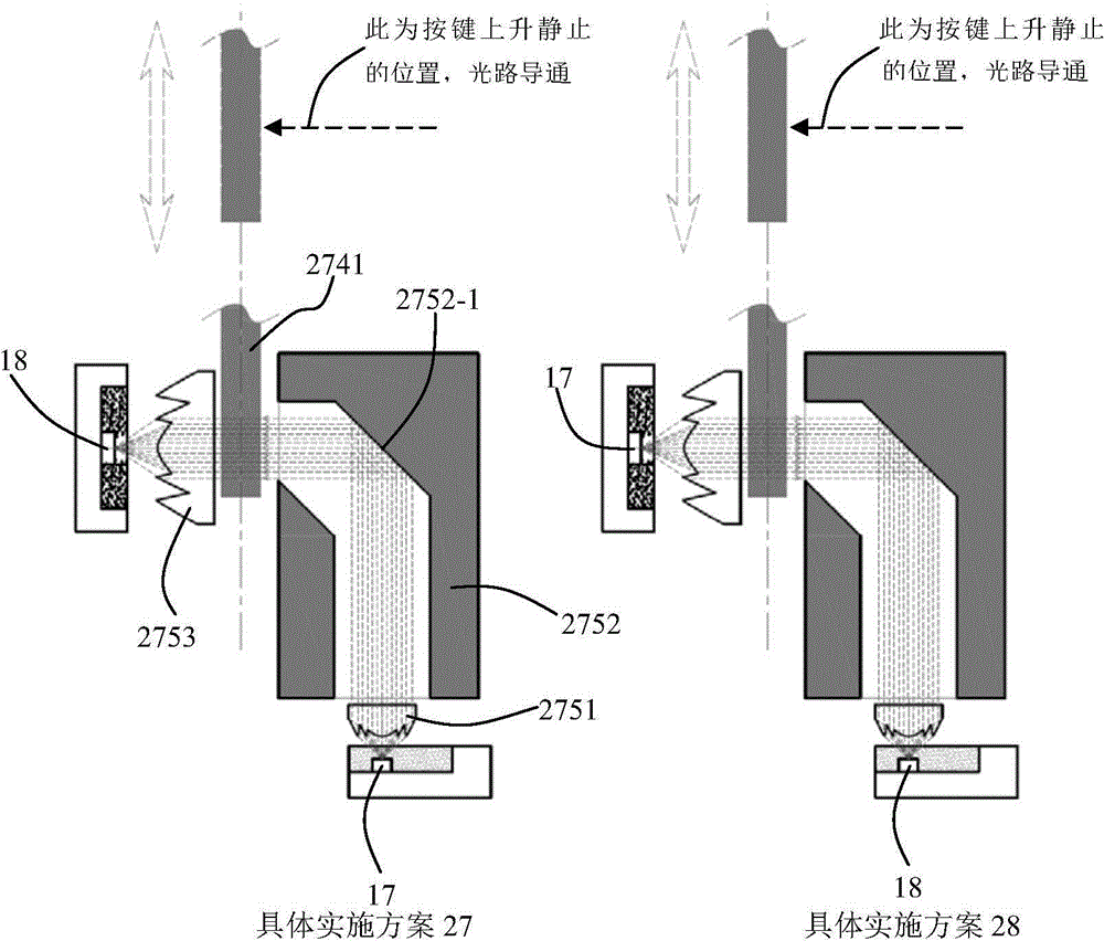
[0087] The light guide system of the button switch used to effectively control and adjust the photoelectric signal involved in the present invention, the switch control principle of its specific embodiment 3 is as follows Figure 10 shown. The light guide 151 above the SMD PT tube 18 on the left side is the same as that of Embodiment 1. The difference in this embodiment is the light-gathering surface 341-3 below the free-form surface condensing prism 341 above the SMD IR tube 17 on the right side. Instead, it has more than one sawtooth-shaped oblique-axis Fresnel surface. The optical axis of the oblique-axis Fresnel surface is CX, and it is inclined toward the direction of the microstructure surface 341-1. The oblique-axis Fresnel surface 341-3 converges the light emitted by the SMD IR tube 17 onto the microstructure surface 341-1. The microstructure surface 341-1 is a zigzag total reflection Fresnel surface, or a microprism array surface with total reflection effect, a micro...

specific Embodiment approach 4

[0090] The light guide system of the button switch used to effectively control and adjust the photoelectric signal involved in the present invention, the switch control principle of its specific embodiment 4 is as follows Figure 11 shown. The converging and turning device on the top of the SMD IR tube 17 on the right side adopts the same free-form surface prism 141 as that of the specific embodiment 1. What is different in this embodiment is that the original light-gathering surface 151-1 on the top of the left side SMD PT tube 18 Instead, it is a condenser lens 452 that is separated from the light guide 451 . The condensing lens 452 is a plano-convex lens or a convex-convex lens, which converges the light in the light guide 451 into the SMD PT tube 18 below.

[0091] Its working principle is: when the button is pressed down, the cross key shaft moves down together with the free-form prism 141, and when it moves to a certain position, the left output end surface of the free-...


PUM


Abstract

The invention relates to a photoelectric light-guide switch module controlling and adjusting photoelectric signals to be input into a device. According to the invention, an SMD IR tube and an SMD PT tube are adopted as an optical signal transmitting and receiving device. A light guide tube or an optical fiber structure is utilized for realizing the switching off and switching on of the photoelectric switch and the precise control of intensity of the photoelectric signals. The photoelectric light guide switch module includes a cross-shaped mechanical shaft, a spring and an upper shell and a lower shell having a buckling lock structure. The switch module also includes the SMD IR tube, a coupling component, a light guide tube or an optical fiber, a focusing part, the SMD PT tube and a prism, a light gate or other switch control components in linkage with a mechanical key shaft. According to the invention, the switching on and off of the photoelectric switch can be realized through moving the switch control component relative to the light guide tube or the optical fiber. Also, linear control of photoelectric signals is realized and game players can feel speed and power in game operation. The switch module is especially suitable for game players.

Description

technical field [0001] The invention relates to a photoelectric light-conducting mechanical shaft keyboard switch and a photoelectric light-conducting game mouse key switch, in particular to a photoelectric light-conducting switch module for controlling and adjusting photoelectric signals for inputting equipment. Background technique [0002] The photoelectric keyboard is a new technology in recent years. It adopts a new photoelectric induction recognition technology, replaces the traditional metal contact shrapnel with an optical induction component, and improves some problems that the traditional contact mechanical switch is easy to wear and damage. It uses the optical principle and photoelectric coupling technology to form a light path between the light-emitting element and the photoelectric sensor. The switch component triggers the photoelectric sensor during the cutting and closing of the optical path, and changes the circuit impedance value to complete the high and low ...

Claims


Application Information

Patent Timeline
Patent Type & Authority Applications(China)
IPC IPC(8): G02B6/42G02B6/35G06F3/02
CPCG02B6/35G06F3/02G10H1/34G02B6/4204G02B6/351G06F3/0202
Inventor 郎欢标
Owner DONG GUAN LONGIDEAL IND CO LTD
Why Eureka
Try Eureka